
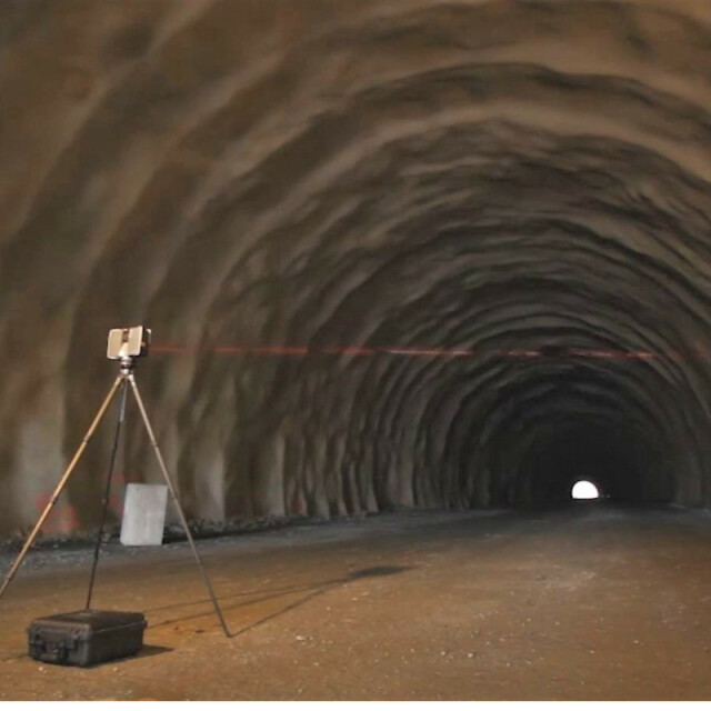
TcpScancyr for Tunnels
Tunnel cross-sections from 3D Scanner
APLITOP
Málaga, ES
Description
Input Data
Horizontal and vertical alignments and superelevation data, via numerical input or conversion from other commercial formats.Theoretical tunnel templates, which can consist of various layers, defined by parameters or by importing a DXF file.
Once this data has been defined, the information from the points taken from the scanner is added via a set of coordinate files either with optional intensity and color.
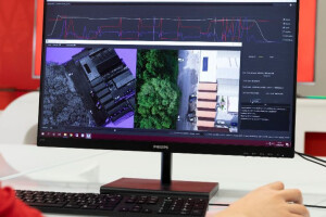
Visualization of Points
Points may be examined using a three-dimensional viewer, with the option of changing between orthogonal and perspective view. Camera position can be controlled directly on the alignment or on a relative position, allowing the station and height to be altered. The level of presentation detail can be modified in order to optimize speed.
The symbology assigned to the points may be configured using a variety of method ssuch as angle, height difference, displacement, natural color, intensity, in/out, etc. The application also includes interactive tools for filtering points based on several criteria.
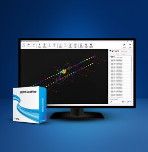
Cross Section Calculation
To obtain cross sections the user needs to specify the station range, the generation interval, and the bandwith to be employed. Optionally the filtering can be activated in order to delete peaks. The program features a powerful profile editor.
Once the cross sections have been calculated, they may be represented in 3D or using a frontal viewer. If the theoretical section has been defined, the over- and under-excavated areas are shown in different colors. Profiles can be exported as DXF files in 2D or 3D, either individually or as sets.
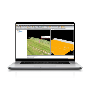
Tools
The program automatically calculates areas, with the option to represent this data on the cross sections or create an area and volume report. The program can also export the drawing as a DXF file, allowing the paper format, scale and other representation options to be set. Tunnel 3D model can also be exported in several formats.
The application also allows the route through the tunnel to be simulated, situating the user at a determined height and allowing him or her to control their position, speed, direction and extent of view.
Specifications
-
Hardware/software requirements
-
RAM [GB]
4
HD [GB]
10
Use of GPU
N
Stereo Display
N
Stand-alone
Yes
-
Other
-
Support
online
Typical applications
Tunnel works control
Distinguishing features
Project definition from alignment, tunnel template and points.Point filtering by height, offset, height difference, distance to template or manual editing.Cross-section calculation and editing.Fully customizable drawing of cross-sections or 3D tunnel.Area and volume, alignment deviation and profile comparison reports.Inspection maps and orthoimages.Video generation.
Training
Y
-
Files and Registering
-
Input formats
TXT,PTS,PTX,FZS,FLS,E57,LAS,LAZ,XCF,CLR,CL3,RDBX
Output formats
DXF,PDF
Max. file size (#3D points)
500000000
Geo-referencing
N
Automatic Target Detection
N
Stitching multiple scans
N
-
Pre-processing and Automatic Filtering
-
Image matching facilities
N
Frequency domain decoding for data reduction
N
Removal of individual outliers
Y
Removal of vegetation
N
Removal of buildings
N
Bare ground DEM generation
N
-
Manual Measurements
-
3D Coordinates extraction
Y
Length and Height
Y
Angle
Y
Distance
Y
Area
Y
Volume
N
-
Interoperability
-
CAD software
AutoCAD, BricsCAD, ZWCAD
Hydrological software
No
Assigning colour from imagery to points
N
Image overlay on TIN
N
Integration with other data types
Alignments, tunnel templates
-
General
-
Year of last update
2019
Year of initial introduction
2010
Modules
Standard or Advanced version
Source of Point Clouds
Airborne Lidar, Indoor TLS, Outdoor TLS, Photogrammetric
Supported Systems
It can process tunnel point cloud files from terrestrial scanners in the supported formats.
-
Analysis
-
Line of sight
N
Aspect and slope
N
Individual tree heights
N
Simulation facilities
tunnel tour,gauge control
Time series analysis
Y
-
Automatically Generated Products
-
Regular Grid DEMs
Y
Cross sections
Y
TIN
Y
Contour Lines
Y
Break lines
N
Boundary detection of solids
N
Building footprints
N
Building roofs
N
3D City modelling
No
-
Solid Modelling
-
Lines
N
Planes
N
Cubes
N
Spheres
N
Cylinders
N
NURBS
N
Industrial features
No
Earth surface features
No
-
Visualisation and Editing
-
Zoom, pan and rotate
Y
Fly-throughs
Y
Adding Points
Y
Removing Points
Y
Point Reduction
Y


