How to Use an Acoustic Doppler Current Profiler For River Measurements
One of the most often overlooked sources of errors or issues with river velocity and discharge measurements using an acoustic Doppler current profiling system (ADCP) is site selection. You can get everything right in regard to the instrument operation, installation, etc., but if you have chosen a site where the basic assumptions of ADCP river measurements have been violated, then you will not get accurate data.
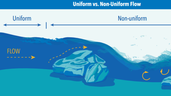
When selecting a measurement site, the goal is to be able to measure velocities that are representative of the mean channel velocity. Ideally, there will be a straight section of the channel of appropriate length that is free from flow disturbance caused by bends in the channel, obstacles in the water, inflows, outflows, etc. A general recommendation is that the measurement or installation location should be at least 5-10 channels widths upstream and downstream Uniform vs. Non-Uniform Flow of any sources of flow disturbance, so that there is sufficient linear distance for any turbulence, eddies, up-welling, backwater effects, etc., to settle out to a uniform, steady flow.
Plant growth in the channel can have an influence on flow conditions, and the bottom topography of the channel can also have an impact, as there could be unseen sources of significant flow disturbance below the water’s surface. The following page contains some interrelated considerations when using a multi-beam acoustic Doppler current measurement system.
Homogenous Conditions
One of the basic assumptions for measuring with any multi-beam acoustic Doppler current measurement system is that the individual beams are measuring in similar conditions so that the velocity averaged from the individual beams will provide an accurate mean velocity.
Spatial Averaging
With a multi-beam acoustic Doppler current measurement system such as the RiverSurveyor S5/M9, SonTek-SL, and SonTek-IQ, the reported velocity is an average of the velocity measured by the individual acoustic beams, which are very narrow.
The reported velocity approximates a spatial average computed from the velocities measured by 2, 3, or 4 beams, and the area-averaged increases with distance from the system. The off-axis beam angle for the SonTek systems is 25 degrees*, so at any specific distance from the system (i.e., range), the beams are separated by (0.93 x range). For example, with the 2-beam SonTek-SL system, at a 10m range, the beams are separated by 9.3m.
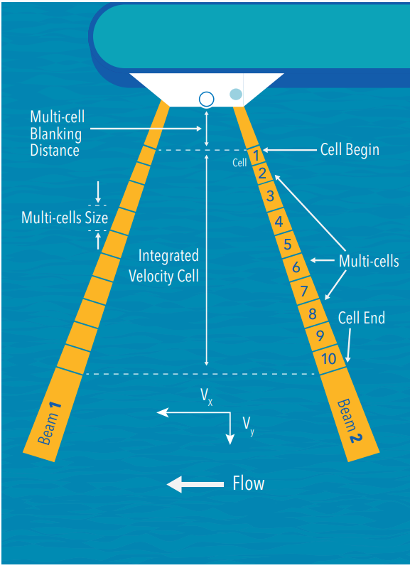
Example of Spatial Averaging for a 2-beam system. * Note: IQ skew beams are 60 degrees off axis.
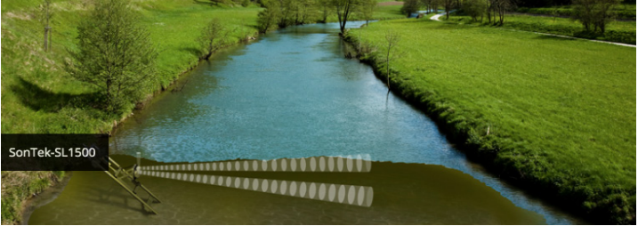
SonTek-SL systems allow for highly accurate measurements anywhere along a waterway.
In measuring various conditions in a channel it would be nice if each one was calm with no obstructions, but it doesn’t always work out that way....
Turbulence / Eddies
When there is significant turbulence or eddies present in the channel, the individual beams may be measured in very different conditions (thus violating the assumption of the homogenous condition), resulting in their averaged velocity being significantly different than the actual mean velocity. For example, there could be situations where a large eddy results in beams measuring velocities in opposite directions, resulting in the averaged velocity being zero. There is usually some level of turbulence or eddies in a channel, especially a natural channel, but averaging the velocity data over an appropriately long period can help to improve the results. Parameters such as Velocity Error and Correlation will give an indication of the homogeneity of the measurement.
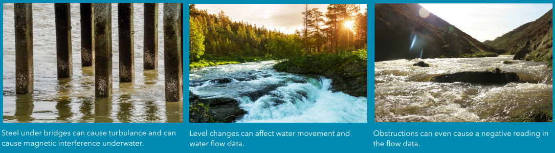
...there could be situations where a large eddy results in beams measuring velocities in opposite directions, resulting in the averaged velocity being zero.
Magnetic Influence
Another site selection consideration is localized magnetic fields, which can affect systems that include a compass, such as the RiverSurveyor S5/M9. Sources of magnetic interference can include steel bridges, the steel rebar used in concrete bridges or structures, as well as power lines. Depending on the available measurement sites, the above recommendations and considerations may not always be feasible. No site is ideal, but it is important to keep the basic assumptions in mind when selecting a site.
Another site selection consideration is localized magnetic fields, which can affect systems that include a compass, such as the RiverSurveyor S5/M9.
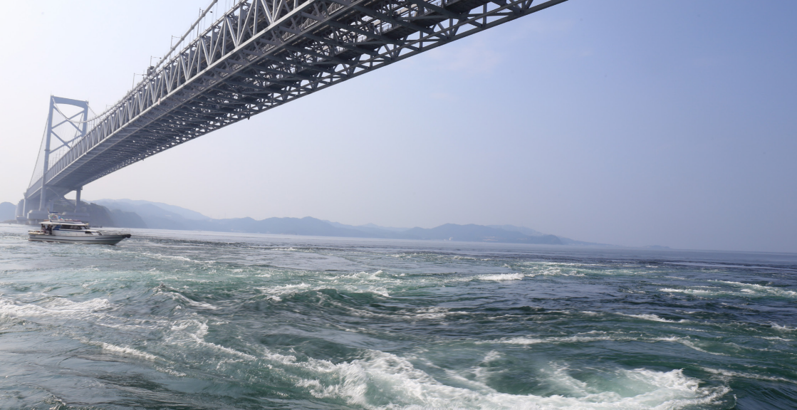
Sources of magnetic interference can include steel bridges, the steel rebar used in concrete bridges or structures, as well as power lines.
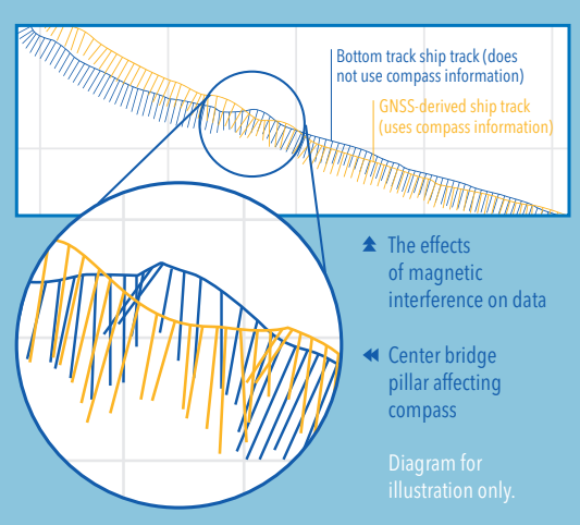
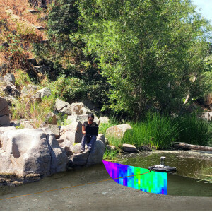
The example above shows the boat tracks with velocity vectors for a river transect, where a nearby bridge pillar caused magnetic interference with the compass.
Do you have questions about this case study?
Get in touch with SonTek, and they would be happy to answer any questions you have about pricing, suitability, availability, specs, etc.


![Do-Giant-Tortoises-Make-Good-Neighbors-1[1].jpg](https://cdn.geo-matching.com/vRMO2Edp.jpg?w=320&s=a6108b2726133ff723670b57bc54c812)


