VectorNav GNSS/INS Systems for LiDAR Mapping
Instead of using a stand alone GNSS and IMU, a more suitable solution for estimating EOPs of the LiDAR sensor is to use a GNSS/INS. The advantages of using a GNSS/INS include a more accurate attitude solution, ability to carry position and velocity updates through short GNSS outages and several other advantages.
What is LiDAR?
Light Detection and Ranging (LiDAR) is a measurement technique that uses light emitted from a sensor to measure the range to a target object. In very simple terms the sensor emits a light pulse and then measures the time taken to receive the reflected pulse in order to estimate the range of the target object, given the constant of the speed of light. Modern LiDAR sensors have multiple lasers or channels, 8 to 128, that are able to produce up to 2.2 million points per second. The LiDAR unit scans from side to side, with some having a full 360 degree horizontal Field of View (FOV), which creates a very dense point cloud that represents the surrounding area.
LiDAR sensors are able to achieve range accuracy of 0.5 to 10mm relative to the sensor and a mapping accuracy of up to 1cm horizontal (x, y) and 2cm vertical (z). This makes them particularly useful as a remote sensing tool for mobile mapping. Additionally, LiDAR sensors are able to collect multiple returns from a single light pulse. This is because as the light pulses travel from the sensor they may encounter several objects that will reflect the pulse such as leaves and branches of a tree canopy. LiDAR sensors are able to record this information to provide a detailed understanding of not only the tree canopy but also the underlying structure. Using these multiple returns LiDAR mapping is able to produce both a:
- Digital Elevation Model (DEM), which is a topology model of the earth’s surface, with natural (trees and other vegetation) and built (buildings, bridges, communication and power lines) objects removed, and a
- Digital Surface Model (DSM), which includes all-natural and built features, e.g. communications lines, bridges, vegetation etc.
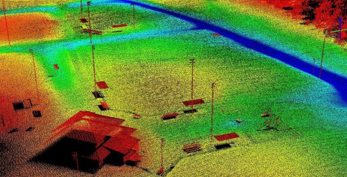
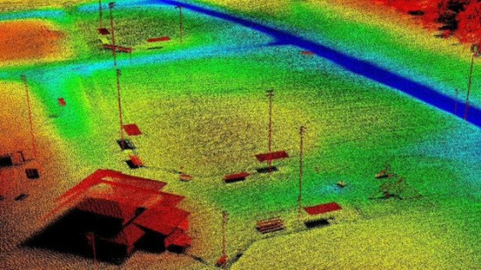
Figure 1: DSM Point cloud
Georeferencing LiDAR Data
Georeferencing is the process of applying a coordinate system to the point cloud so that it can be accurately located on a map. In order to georeference the point cloud the LiDAR sensor’s orientation and position, or Exterior Orientation Parameters (EOP), need to be known in order to create a planimetrically correct scan that can be used for Geographic Information System (GIS) analysis.
Unlike photogrammetry where Ground Control Points (GCPs) can be used to georeference mapped data using Aerial Triangulation. Ensuring that LiDAR data is accurately georeferenced requires the use of Direct Georeferencing, using an accurate GNSS receiver and an inertial measurement unit (IMU) measure the pose (orientation and positing) of the LiDAR sensor.
To accurately georeference LiDAR data, operators need to take particular care when configuring the mapping system. Any misalignments or offsets incorrectly configured will directly impact the accuracy of the point cloud. There is little that post-processing can do to resolve errors and will most likely result in having to remap the environment/scene. When configuring the mapping solutions it is important to ensure that the following are correctly configured:
- Boresighting - this is the process of aligning the LiDAR sensor axes with the IMU axes.
- GNSS Antenna Offset - because the GNSS Receiver calculates the geographic coordinates at the antenna phase centre we need to map this to the IMU origin. The GNSS lever arm needs to be configured in the IMU reference frame for x, y, z offset
- Reference Frame Rotation - The IMU coordinate frame may not align with the vehicle frame. It is therefore important that the IMU frame be mapped to the vehicle frame in order to ensure that the georeference data is correctly applied
Finally, we need to implement synchronization to ensure that each range measurement is correlated with the correct pose data. LiDAR sensors typically have the facility to accept a time synchronisation pulse, such as a Pulse Per Second (1PPS), from the GNSS receiver and NMEA timing data.
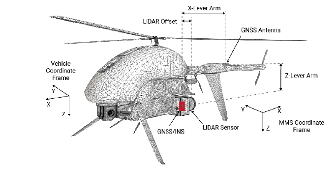
Figure 2: MMS Reference Frames and Offset calibration
LiDAR Mapping Application Note
Learn more about the advantages of LiDAR over other surveying methods, the practical implementation of using LiDAR for surveying and the impact of GNSS/INS precision on LiDAR mapping accuracy. Please download VectorNav's application note.
Sensor Selection for Direct Georeferencing LiDAR Data
Instead of using a stand-alone GNSS and IMU, a more suitable solution for estimating EOPs of the LiDAR sensor is to use a GNSS/INS. The advantages of using a GNSS/INS include a more accurate attitude solution, ability to carry position and velocity updates through short GNSS outages and several other advantages. To learn more about how a GNSS/INS operates please read Section 1.7: GNSS-AIDED INERTIAL NAVIGATION SYSTEM (GNSS/INS) in the VectorNav Library.
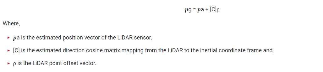
Using a GNSS/INS allows for all points in the point cloud to be geo-referenced to a fixed global reference frame. The following equation can be used to solve the absolute position of a point on the ground:
Attitude Errors
Any angular uncertainty projects to the positional error based on the distance from the point to the LiDAR sensor. Therefore to achieve the required mapping accuracy, the attitude (Pitch/Roll) accuracy required is a function of the mapping height. The higher the altitude the greater level of attitude accuracy required.
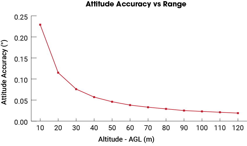
Figure 3: Attitude accuracy requirement vs range for 4cm point cloud accuracy
Positioning Errors
Positioning errors come from the uncertainty in the position of the GNSS/INS sensor. This position uncertainty is represented in the North, East, Down (NED) coordinate frame The position uncertainty is mostly determined by the accuracy of the GNSS solution alone.
In order to achieve survey-grade results, it is necessary to use GNSS Receivers capable of either Real-Time Kinematic (RTK) or Post-Processed Kinematic (PPK) corrections to determine image coordinates to less than 1cm. As there is little need for Real-Time mapping, most LiDAR mapping operators opt for PPK which has advantages of simplified operation and provides more accurate positioning data compared to RTK by utilizing precise satellite ephemeris data and forward/backward smoothing techniques.
Do you have questions about this article?
Get in touch with VectorNav Technologies, and they would be happy to answer any questions you have about pricing, suitability, availability, specs, etc.
Related articles


