TcpStereo
Vector restitution in stereo on CAD platform of oriented aerial photographs
This application allows stereo plotting in any CAD platform using aerial photographs with previously defined orientations. It is especially useful for photogrammetric surveys with drones and can be used by public administrations, and companies specialized in mining, earthworks, hydrology, environment, urban planning and many more.
APLITOP
Málaga, ES
Description
TcpStereo
Stereo plotting over orientated photographs
Introduction
This system allows stereo plotting in CAD platform over aerial photographs with previously defined orientations.
It works from simple anaglyph glasses to professional stereoscopic vision hardware, and it’s specially useful for photogrammetric surveys made with drones. It also can be used by public administrations, mining companies, landslide, hydrology, environment, town planning, etc.
Data Entry
We must give the folder containing the image files and other data depending on the kind of project.
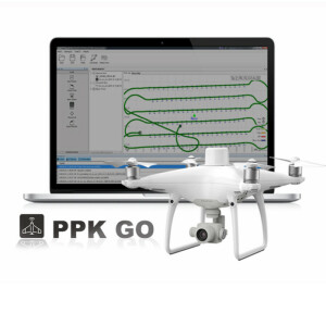
Digital flights
We only have to import the exterior orientations file, and we will obtain automatically the camera parameters from the metadata contained in the photographs.
Different formats of exterior orientation file are admitted so the user can specify the columns that correspond to the photo-centers coordinates and the angles of rotation of the camera for each photography.
To finish the process of import, the parameters of the camera, the average height of flight and terrain are validated.
Analog flights
In this case we will import one internal orientation file of Digi3D for image and one file with the exterior orientations. For it we have to specify the flight and other parameters of the camera such as, the focal length, the principal point, heights of flight and terrain.
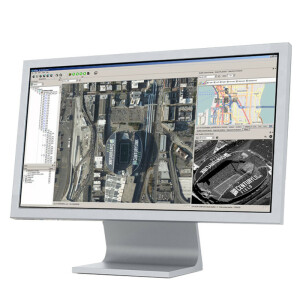
Images Management
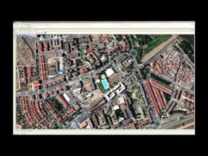
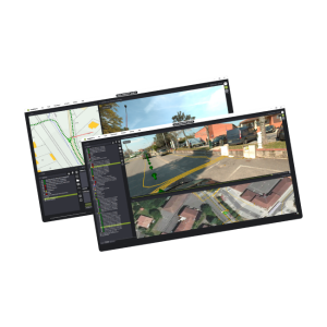
In the definition of the project, the images are converted to a pyramidal format to optimize the output during the visualization. The images are organized in strips, models and block, which can be activated simultaneously in different windows of the application.
In the toolbar we find tools for zoom, pan, scale change, mini-map. Also it allows copying the current image to the clipboard or recording it in disk.
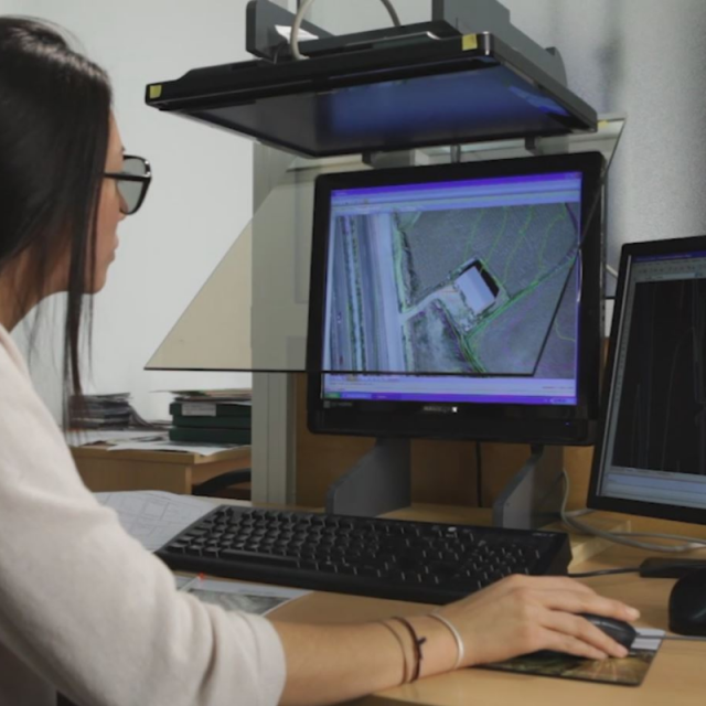
The models can be visualized in stereo by low cost systems based on transmitters and active glasses, or mirrored screens and polarized glasses. Also it allows the pseudo-stereo view (superposed images) in conventional equipments, and can be viewed stereo using anaglyph glasses (two colors).
With the program we can see several stereoscopic models at the same time, pass automatically from a model to another one following the movements of the user in the terrain. And also it is possible to know the real coordinates of the terrain and the height; also we can measure 2D and 3D distances, slopes and elevation differences, perimeters and areas.
Configuration
We can personalize some characteristics of the application: the functions of the keyboard, speeds of the displacements in horizontal, vertical and height, the properties of the cursor (form, size, color, height text, etc.), and the way CAD drawings are represented on the stereo.
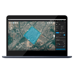
CAD Synchronization
The program can be synchronized with some versions of AutoCAD and Bricscad, and by this way we can draw objects with constant or changeable height by means of the stereo mode and with the same coordinates.
In addition a drawing can be loaded in the CAD. Over the stereo model the drawing´s layers in which the user is interested can be showed, supporting the pan and center of the drawing automatically.
Over the stereo viewer we can:
* Measure 2D and 3D distances
* Measure slopes and elevation differences
* Measure a 3D perimeter and the area contained in it
* Place the viewer in specific terrain coordinates
We can do the following functions in the CAD from TcpStereo:
* Rotation of the drawing: It turns the view of the drawing in the CAD to make it coincide with the stereo model´s one.
* Show drawing: It shows the selected layers of the CAD´s drawing on the stereo.
* Simple Drawing: draw 3D points and polylines in the CAD from points designated on the stereo model.
* Continuous Drawing 2D: It allows drawing 2D polylines in the CAD moving the mouse (sketch), from some functioning parameters given by the user. It is suitable for the creation of contours.
* 3D Continuous Drawing: It allows one to draw 3D polylines in the CAD moving the mouse and changing the height, interpolating the height of the points of the polyline depending on the points designated by the user
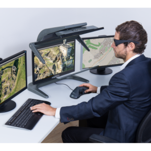
Stereoscopic Vision Systems
There are two kinds of stereoscopic vision systems:
* Passive systems, which uses polarized glasses or glasses with filter.
* Active systems, which uses shutter glasses, an IR emitter and a high frequency monitor (100 – 120 Hz).
In the first category, and using common graphic cards, it can be used the anaglyph method, consisting on multiplexing a pair of images by wavelength using colored filter glasses (usually red and cyan, red and green or red and blue).
Among passive stereo systems we can also find solutions consisting on a polarized monitor and polarized glasses, giving horizontal interlaced stereo.
Another passive system is based on two conventional LCD monitors placed in right angle, with a polarized crystal mirror in its bisector, a signal inverter and polarized glasses, giving stereo by cloning video signal.
Among active systems, there are several solutions in market, for instance NVidia 3D Vision system, which allows to see stereo with a variety of Nvidia graphic cards and high frequency LCD monitors.
Specifications
-
Feature Extraction and Mapping
-
Mapping facilities
Y
Semi-automatic corner point extraction
N
Semi-automatic line feature extraction
N
Semi-automatic building extraction
N
3D superimposition
Y
Integration with scanned maps
N
Integration with 2D vector maps
N
Integration with 3D vector maps
Y
Integration with point clouds
N
Automatic texturing
N
-
Required Computer System
-
System includes hardware
N
Operating system(s)
Windows
CPU (min.)
Intel Dual Core
Min. RAM memory [Mb]
2048
Preferred RAM memory [Mb]
16384
Min. data storage capacity [Gb]
10
Preferred data storage capacity [Gb]
20
Min. graphic card
NVIDIA Quadro FX
Supported special hardware
Volfoni RF emitter (ActivHub RFOne or RF50) and Volfoni EDGE (RF or VR) shutter glasses
64-bit version of software available
N
Distributed processing capacity
N
GPU based calculations
N
Hardware handling of big data sets
NVIDIA Quadro FX
-
Images and data
-
Source data
Digital flights, Analogue flights, Pix4D and Agisoft Fotoscan processed images
Input image formats
TIFF, JPEG
Export data formats
DWG
Scanned analogue Aerial Photos
Y
Digital Aerial Nadir Frames
Y
Oblique Images
N
Linear array sensors
N
Optical Satellite Images
N
UAS Images
Y
Radar Images
N
-
DEMs & Orthoimages
-
Automatic breakline extraction
N
Checking facilities (DEM editing)
N
Automatic contour generation
N
Mosaicing of orthoimages
N
True orthoimage generation
N
Dense DSM creating capability
N
DSM to DTM filtering
N
Automatic seam line creation
N
Dense Image Matching
N
-
Viewing System
-
Min. display memory [Mb]
1024
Pref. display memory [Mb]
2048
Resolution
1024x768 minimum
Method of stereo image separation
Anaglyph glasses, high frecuency monitor with shutter glasses, interlaced stereo monitor with polarized glasses, system with two monitors, a crystal mirror and polarized glasses
-
General
-
Year of introduction
2010
Year of last update
2021
Modular
Active and passive stereo systems
License configuration
Evaluation, Commercial
Regional settings available
Español / English
-
Orientation and triangulation
-
Automatic interior
N
Relative
Y
Automatic aerotriangulation
N
Automated blunder detection
N
Self calibration
N
Automatic Relative
No
images simultaneously processed
N
-
Measurement tools
-
Length
Y
Area
Y
Volume
N
-
Image manipulation & processing
-
Automatic contrast manipulations
N
Spatial convolution
N
Radiometric corrections
N
Radiometric adjustment for mosaicing
N
Resampling
Y
-
More information
-
Main applications
This system allows stereo plotting in CAD platform over aerial photographs with previously defined orientations. It is specially useful for photogrammetric surveys made with drones, and it can also be used by public authorities, mining companies, landslide, hydrology, environment, town planning, etc.
Distinguishable features
Low cost and easy to use applicationAnalogue and digital flights, Automatic conversion of Pix4D and Metashape processed images, Measure of 3D distances, areas and elevation. Drawing of 3D entities synchronized with AutoCAD or BricsCADLoading of cartography drawings over stereo model


![ELCOVISION-10[1].jpg](https://cdn.geo-matching.com/wRWm7Gyp.jpg?w=300&h=300&crop=1&s=d9595e4eab382ce38f888d623cb550d7)


