
Using Laser Rangefinders in Vegetation Management
Ground truth your clearances to confirm your data and during your ground patrols to reduce your vegetation management costs. With an LTI TruPulse 360 laser rangefinder compass laser in hand, vegetation management professionals can now avoid violations and create a process that is reliable, cost-effective and most importantly, safe.
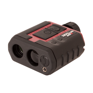
Using the TruPulse 360 in conjunction with Lidar scans or PLS-CADD models helps to streamline the vegetation management process. The single push of a button allows professionals to measure distance, inclination, height, azimuth and more. With LTI's exclusive TruVector 360° Compass Technology built-in, the TruPulse 360 can even instantly calculate clearance values and provide the best possible azimuth accuracy, no matter what pitch or angle the laser is shot from.
This technology provides a simple way to ground-truth clearances and offers electric utilities a resourceful way to avoid violations by visiting specific problem areas located directly on the ground, preventing missed hazards and eliminating huge fines.
Ground Truthing Your Clearances
- Laser-based technologies can measure distance, height, azimuth, horizontal angles, and missing line values, and can simplify vegetation management and pole audits.
- Historically, transmission line owners have used a variety of clearance criteria.
- Today, NERC requires vegetation management that prevents encroachments under all expected line positions.
- Lidar data and PLS-CADD models help transmission owners comply with NERC requirements.
- El Paso Electric uses ground patrols, aerial Lidar, and area-specific field inspections to manage vegetation on transmission line corridors.
- Transmission line owners must be aware of two regulations affecting vegetation management.
Overview
Keeping in compliance with vegetation clearance mandates from regulatory agencies is easier said than done. Electric utilities must understand the rules and regulations and must implement a vegetation management process that is consistent, efficient, safe, and cost-effective. Laser-based technologies, Lidar scanning, and PLS-CADD models are proven methods that support vegetation management. These approaches have been used successfully by utilities of all sizes.
Context
A panel of experts discussed how transmission line owners can leverage technology to develop an efficient, safe, and cost-effective vegetation management process.
Key Takeaways
Laser-based technologies can measure distance, height, azimuth, horizontal angles, and missing line values. Lasers can measure many dimensions that are essential for electric utilities.
Examples include:
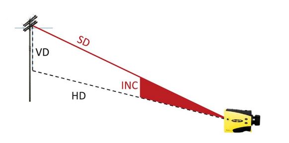
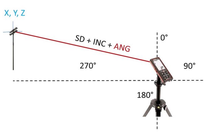
Distance. With a laser sensor, users can shoot to the top of poles. The sensor measures the slope distance (SD) and degree of inclination (INC). A built-in inclinometer calculates the vertical and horizontal distances (VD and HD). The resulting data represents the true distance from Point A to Point B, regardless of the inclination used for the initial shot.
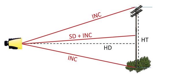
Height. Laser sensors can also calculate height. As long as a clear line of sight exists, the sensor will measure the slope distance and degree of inclination. The next two shots gather inclination values, used to compute an exact height.
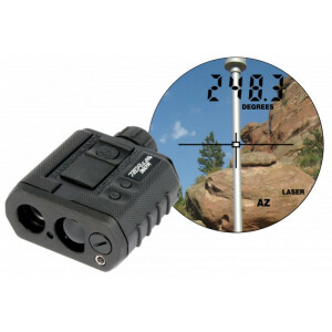
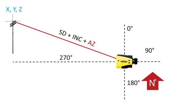
Azimuth. All-in-one integrated compass lasers provide true vector compass technology. The user takes a shot that captures the slope distance to re-inclination and the azimuth value. Depending on the direction relative to magnetic north, it is possible to calculate the X, Y, and Z values of the shot.
Horizontal angle. This approach derives the X, Y, and Z value from any zero reference point. Unlike azimuths, horizontal angles aren’t necessarily correlated with magnetic north.
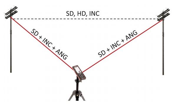
Missing line value. This calculation is useful for vegetation management because users can stand far away and obtain highly accurate span values. It is derived with a compass or a horizontal angle calculator. The user takes two shots that capture the slope distance, inclination, and angle. The horizontal, slope distance and degree of inclination between the two shots are calculated.
Laser-based tools simplify vegetation management and pole audits. Laser Technology offers applications and sensors that electric utilities can use for vegetation management and pole audits. Offerings include
- Robust pole audit workflows. Integration between lasers and smartphone apps supports pole auditing.
- T&D engineering. Laser Technology provides a solution that includes software to compute key values for T&D engineering. Users can shoot along the conductor line and calculate sag and tension values.
- GIS mapping. Laser Technology’s GIS mapping application integrates with GPS receivers.
''Laser Technology is celebrating its 30th year in business. The company developed the first recreational range finder and pioneered the first GPS Laser Offset.'' Paul Adkins
Historically, transmission line owners have used a variety of clearance criteria. Historically, transmission line owners have utilized many types of clearance criteria. Four examples are:
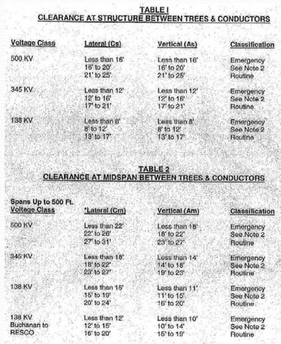
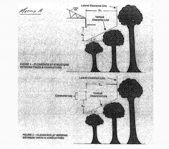
1. Clearances between trees and conductors. For each voltage class, transmission line owners specify a horizontal and vertical component for clearance at the structure between trees and conductors, and for clearance at the midspan between trees and conductors. The goal is to determine violations and the urgency for resolving them.
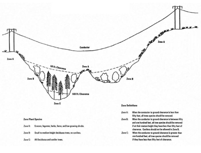
2. Viewing the top of vegetation. Some transmission line owners specify vegetation in violation by standing at the center line and looking at a specific viewing angle to the tops of the vegetation.
3. Specific clearance zones. In some cases, transmission line owners specify wire zones, border zones, or other metrics to assess risk levels.
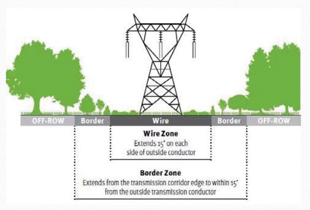
4. Unique clearance zones. Some transmission line owners specify unique clearance zones which eliminate possible areas from consideration. This approach also reduces vegetation management costs.
Today, NERC requires vegetation management that prevents encroachments under all expected line positions. The North American Electric Reliability Corporation (NERC) specifies in Docket No. RM12-4-000-34 that conductor movements must be taken into account under FAC-003-2. In addition, transmission owners must show that their approach to vegetation management under Requirement R3 will prevent encroachments under all expected line positions.
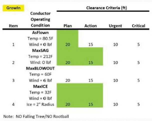
Transmission owners must manage vegetation so it doesn’t encroach into the MVCD (Minimum Vegetation Clearance Distance) under multiple operating conditions. These include MaxSAG, MaxBLOWOUT, and MaxICE. As a result, transmission owners must determine the minimum distance between conductors and vegetation at various positions in the right of way. Lidar data and PLS-CADD models help transmission owners comply with NERC requirements. When measuring the distance between trees and conductors, it is impossible to view the conductors based on diverse operating conditions. To address this problem, conductors must be modelled. Ways in which Lidar data and PLS-CADD models can help include:
Lidar data identify potential violations. Using AsFlown operating conditions from Lidar data, it is possible to analyse MaxSAG, MaxBLOWOUT, and MaxICE risks for Grown violations.
FallIn violations are strongly influenced by the terrain. It is possible to take cross-sections through the right of way maps to capture the potential FallIn locations along a particular line. After combining those profiles, a continuous clearance surface can be generated.
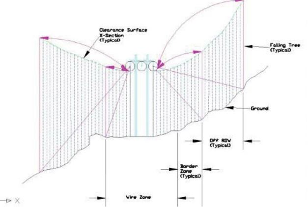
It is also possible to apply two-dimensional contour maps to clearance surfaces to illustrate isolines on the surface. This data can be taken to the field to identify whether or not trees are a violation. This is useful for FallIn and GrowIn clearances.
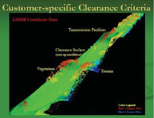
- Lidar and PLS-CADD technologies create clearance surfaces. Most utilities have Lidar surveys which define the exact geometry and location of vegetation, as well as the conductors and structures supporting conductors. With that, it is possible to build a PLS-CADD model that includes a digital terrain model and accurate geometry of the conductors. This information can be taken to the field using tablets or smartphones.
''The Lidar data is where we get the actual location of the vegetation that violates the criteria and the PLS-CADD model gives us the location of the conductors under those operating conditions.'' Jim Dow
- Aerotec’s TopGun simplifies field inspection. TopGun integrates Laser Technology’s TruPulse 360 Rangefinder with a GPS unit and handheld computer. Users take a single shot of vegetation and let the model work. The resulting data can be transferred to work management or GIS software.
- Reverifications may be done using FODAR. This technology uses a camera to create 3D point clouds which can be passed to PLS-CADD for analysis.
El Paso Electric uses ground patrols, aerial Lidar, and area-specific field inspections to manage vegetation on transmission line corridors.
El Paso Electric generates, transmits, and distributes electricity to approximately 400,000 customers in Western Texas and Southern New Mexico. The company has a net dependable generating capability of 2010 megawatts and its transmission system is composed of 1,700 miles of lines that range in voltage from 345kV to 115kV and 69kV. The transmission lines span deserts, forests, farmland, and urban areas.
In addition to complying with NERC requirements, El Paso Electric conducted a minimum approach distance study. Based on the results, it developed a minimum vegetation clearance distance. The tools used to support vegetation management include the Aerotec TopGun Veg-tool, Lidar surveys, and PLSCADD software. The company uses three processes:
- Ground patrols. Patrols identify potential vegetation encroachment and ROW clearing requirement. The 345kV lines are patrolled twice a year, while the 115 kV and 69kV lines are patrolled annually.
- Aerial Lidar. This provides high-accuracy vegetation identification and historical data sets for analysis purposes.
- Area-specific field inspections using the TopGun. Inspections offer the flexibility to analyse the corridor at any specific location and to conduct specific vegetation encroachment inventories.
''The Aerotec TopGun works really well for us. It allows us to identify FallIn and GrowIn trees that might be in our right of way.’'. - David Gamon
Transmission line owners must be aware of two regulations affecting vegetation management.
Two regulations affecting vegetation management are
- FAC-003-3. This regulation outlines several requirements for all lines that are 200kV and above, as well as for lower voltage lines that are critical to the national grid. These include:
- Annual planned and documented inspections
- Prevention of encroachments of Minimum Vegetation Clearance Distance
- Prevention of fall-in from outside ROW
- Prevention of conductor blow-out to adjacent vegetation
- Consideration of conductor movement (i.e., sag and sway) - FAC-008. This regulation addresses facility ratings and construction. Utilities must ensure that facilities are rated according to field as-built conditions and must have a technically sound method for evaluation. Lidar and PLS-CADD models may be developed that detail the condition of transmission facilities under different types of loading. Once built, these models can be used in subsequent years.
Although FAC-008 was estimated to cost the industry between $100 and $200 million to develop, those costs didn’t relate to vegetation management. In 2010, NERC indicated that models developed for conductor sag and sway can be used by vegetation managers for analyses related to FAC-003-03, assuming that no construction changes have occurred. This means that faster and less expensive Lidar flights can be used for vegetation management, and models don’t have to be rebuilt every time.
''When you’re on the ground, you don’t know what the sag and sway of conductors have the potential to be depending on environmental conditions. It really depends on what’s going on during high loading and storm conditions. Technology allows us to view what foresters can’t see on the ground.'' Vince Mikulanis
Two case studies illustrate how technology can help with inspections
Utility’s Transmission and Engineering (T&E) Department Conducts Lidar Flights for Equipment Inspections
The Vegetation Management (VM) department receives a copy of the data from T&E Lidar flights. Although flights aren’t frequent enough to incorporate into the Transmission Vegetation Management Program, the VM team uses the data for ancillary purposes.
Vegetation data is analyzed as a “sanity check” to confirm the success of annual ground patrols and vegetation work. Data sharing between the T&E and VM departments reduce costs. The organization is adapting field software to receive Lidar data for field use.
Full Implementation of Advanced Technologies
A large utility with many NERC-rated lines developed a partnership with a Lidar provider, software developer, and Davey Resource Group. A solid partnership has been essential for integrating new technologies and developing new processes.
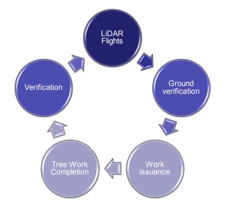
The approach has five elements:
- Annual Lidar flights. The resulting data is analyzed and imported into the software to identify existing and potential GrowIn detection. The infra-red band from the imagery identifies unhealthy trees.
- Ground verification. Consulting Utility Foresters (CUFs) are routed to locations with detections. They evaluate detections and look for potential misses. CUFs also explain the removal programme to property owners, negotiate removals, and provide location information in the software for contractors.
- Work issuance. Contractors use information from CUFs to access tree locations.
- Tree work completion. A “bread crumb” trail provides the most direct access to contractors, so work can be completed efficiently.
- Verification. Contractor work is verified. As the process evolves, procedures are continually undergoing improvement. Advantages include faster and safer inspections, improved crew routing, and continuous learning.
Do you have questions about this article?
Get in touch with Laser Tech, and they would be happy to answer any questions you have about pricing, suitability, availability, specs, etc.

