Installing, Calibrating, and Testing a POS MV Oceanmaster System for Hydrographic Surveys
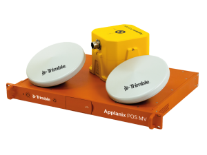
As with most new vessel charters, A-2-Sea were starting from scratch when mobilising the Noortruck with their new Applanix POS MV OceanMaster, so careful consideration was required for sensor location. The placement of GNSS antennas, IMUs and sonar equipment can directly affect system performance.
A precise and thorough dimensional control survey, sensor calibrations and equipment verifications are vital for quality hydrographic data production. The Applanix POS MV OceanMaster is ideally suited to a vessel the size of Noortruck due to the accuracy the system provides over longer lever arms.
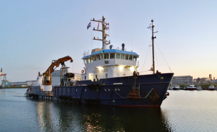
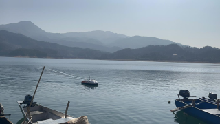
Figure 1: The Noortruck was mobilised in Germany with the Applanix POS MV OceanMaster. The vessel will allow A-2-Sea to fulfil its offshore survey requirements.
How the Inertial Measurement Units (IMUs) are Being Installed
To ensure redundancy, A-2-Sea identified two IMU locations on the vessel. The primary IMU was installed in a location that was identified as secure, elevated above the deck and close to the centreline and centre of rotation of the vessel. A-2-Sea Design Engineers measured and designed an aluminium plate and box to support, secure and protect the IMU. The Applanix base plate could then be secured onto the aluminium plate before being boxed in.
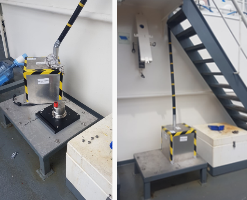
Figure 2: Applanix IMU mounting location with protective covering and cable routing solution.
A secondary IMU location was also identified in the cofferdam space (under the wheelhouse). This was identified as secure, protected and close to the centreline and centre of gravity. It was positioning this location close to the entrance to the cofferdam allowed for clear line-of-sight access for the dimensional control survey. Again, an aluminium plate was designed by A-2-Sea engineers as an intermediate plate between the cofferdam deck and the IMU plate. The secondary location allowed for redundancy should there be any issues with the primary location.
The Applanix Mounting Plate is a bespoke design that accommodates various IMU types. The principle behind the design means that surveyors can survey in the mounting plate, giving them the flexibility of swapping out IMUs without having to re-survey misalignment angles or offsets.
A-2-Sea had the luxury of two locations and two mounting plates, giving them flexibility.
Installing GNSS Antennas
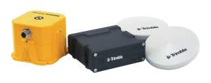
The Applanix POS MV OceanMaster uses GAMS (GNSS Azimuth Measurement Subsystem) to aid the IMU in heading calculations. This unique feature uses two GNSS antennas to determine a GNSS-based heading that is accurate to 0.01deg when blended with the inertial navigation solution.
To optimise antenna location, A2Sea engineers were required to develop a design to ensure a secure and rigid mounting location, free from external interference.
Multiple antenna mount points were made available and measured to provide options and backups.
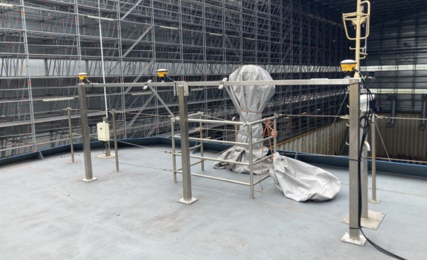
Figure 3: A-2-Sea designed an antenna mounting frame to provide an optimal location for GNSS data reception.
Dry Dock Dimensional Control Survey
The installation on the Noortruck occurred with the vessel in the dry dock. Ensuring a stable platform to carry out precise total station Dimensional Control Survey.
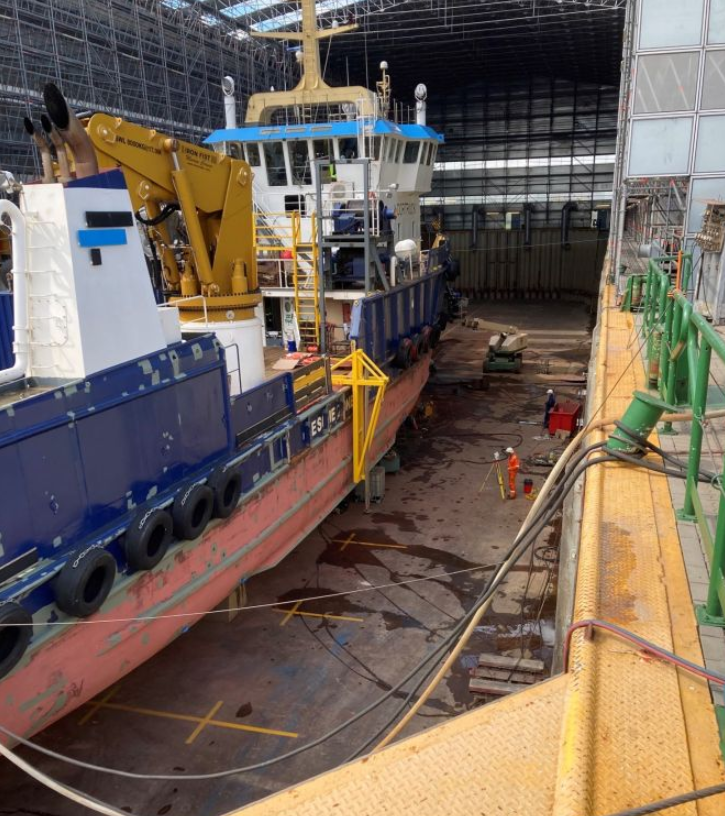
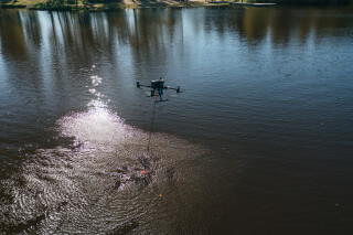
Figure 4: A surveyor conducting a dimensional control survey of the Noortruck
Surveyors adopted the technique of defining a vessel reference frame and then establishing sensor locations and rotations concerning that vessel reference frame (VRF).
A Common Reference Point (CRP) was defined as the target on the IMU housing, with all sensor offsets measured relative to this location. As well as sensor offsets, the vessel Centre of Rotation (COR) was also defined, which is key for optimal Heave measurements.
All total station coordinates were within ±0.5mm for each ordinate, these values were obtained by observations from multiple station setups, and the mean obtained showed, on average, a standard deviation of 0.5mm.
During the measurement process, permanent and recoverable control points were defined throughout the vessel within the specified tolerance of ±0.01m relative (at the 95% confidence level) in X, Y and Z.
Similarly, all sensors were established within the VRF to within a tolerance of ±0.02m relative (at the 95% confidence level) in X, Y and Z.
The final step was to determine the IMU frame about the vessel frame. By extending the baseline of the IMU plate, the misalignment angles were determined. The IMU mounting plate has precisely machined grooved sides in the X and Y directions allowing a bar to be placed along these edges to increase the baseline length with which the mounting angle is measured. The longer this baseline, the more precisely the angular component can be computed from the 3D coordinate values.
Verifying the Measurements
GAMS
During the Dimensional Control Survey, the Primary and Secondary antenna locations were precisely measured and the X, Y, Z baseline vector components were determined.
To verify these measurements, a dynamic GAMS calibration was completed at sea. By starting with zero values in the GAMS parameter setup, a series of dynamic manoeuvres were completed, allowing the POS MV to calculate the GAMS parameters automatically. The results from the dynamic calibration were within close agreement with those measured in the dimensional control:
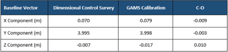
Table 1: A comparison of GAMS baseline vectors from the dimensional control survey and dynamic GAMS calibration. Small residuals validated the dimensional control-derived figures.
The values from the Dimensional Control were used going forwards as these were deemed more precise. The dynamic GAMS calibration depends on quality GNSS measurements and sufficient vessel dynamics, which can often be hard to achieve on larger vessels. Hence, the GAMS calibration process acts as a validation, checking for gross errors in the dimensional control survey.
Checking the Positions
Whilst alongside, position checks were carried out using RTK-enabled Leica GNSS receivers. The GNSS antennas were placed at previously measured control points, and position data was logged. These control points were also defined as nodes in QPS QINSy software, to which the POS MV data was interfaced.
The POS MV was utilising the real-time Trimble RTX correction service data delivered over L-Band, to provide centimetre-level accuracy.
Trimble RTX provides centimetre-level accuracy on a global level. Trimble RTX utilises real-time satellite measurements from a global network of tracking stations, along with highly accurate atmospheric models and algorithms to generate Trimble RTX corrections. These corrections are then broadcast to the receiver via geostationary satellites or over the internet.
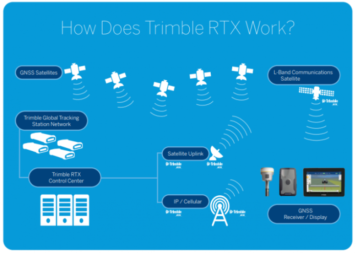
Figure 5: Trimble RTX, a globally available network providing centimetre level corrections over L-band satellite and internet.
A comparison of RTK GNSS data and POS MV GNSS aided inertial data, translated to nodes within QINSy, showed a close agreement, meeting the project specification.
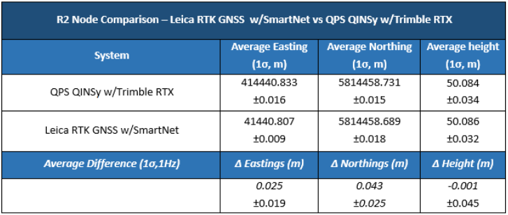
Table 2: The position verification results comparing the RTK GNSS with the POS MV position solution.
With the POS MV installed, calibrated and verified, further sensor calibrations specific to the project were carried out.
Continuing the Work
The Noortruck is currently engaged in nautical charting work for the Civil Hydrography Program off the East coast of the UK.
As part of a collaboration between Applanix, Trimble and A-2-Sea, Trimble RTX was activated over L-Band through POSView, the control software for the POS MV OceanMaster.
With a fast convergence time, the system achieved centimetre-level accuracy within minutes of activation. The Trimble RTX solution allowed A-2-Sea to complete calibrations and verifications and provide an accurate real-time solution during survey operations.
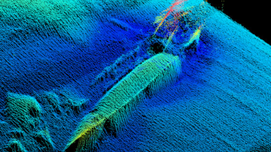
Part of their ongoing survey scope is to report uncharted features on the seabed within a strict 24-hour time frame; the POS MV with Trimble RTX corrections allowed them to do this with confidence.
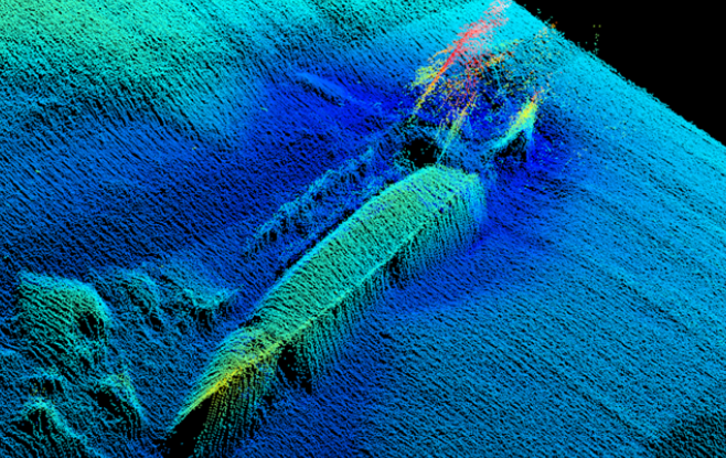
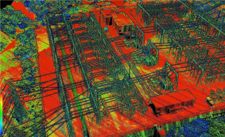
Figure 6: Multibeam data showing a distinct seabed feature. The robust and accurate solution provided by the POS MV OceanMaster, in combination with Trimble RTX, allows confident validation and identification of existing and new seabed features.
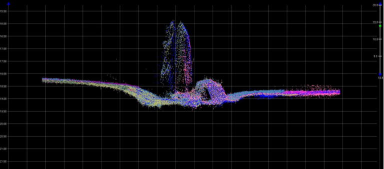
Figure 7: Seabed features also provide a useful tool for calibration and verifications. This image shows the alignment of multiple Multibeam swaths over a feature, confirming angular misalignments have been correctly applied during the Multibeam Patch Test.
The Conclusion
A-2-Sea successfully completed the mobilisation of their Applanix POS MV OceanMaster on the Noortruck, taking careful consideration of sensor location, undertaking a precise and thorough dimensional control survey, sensor calibrations and equipment verifications, ensuring the acquisition of high-quality hydrographic data.
The successful cooperation between Applanix, Trimble and A-2-Sea allowed the testing of the Trimble RTX correction service, which will provide valuable data as the solution becomes more available to the marine market.
About the Authors
Nick Smart – Technical Sales Support, Applanix.
Nick is an experienced Hydrographic Surveyor with over 10 years of experience. He joined Applanix in 2020 to provide pre-sales support.
Liam Flynn – Survey Operations Manager, A-2-Sea
Liam is an experienced Hydrographic Surveyor with over 8 years of experience. Liam has been managing the survey department at A-2-Sea since 2019.
Do you have questions about this case study?
Get in touch with Trimble Applanix, and they would be happy to answer any questions you have about pricing, suitability, availability, specs, etc.


![3月21日-封面[1].jpg](https://cdn.geo-matching.com/voeE1ywo.jpg?w=320&s=6b3b1a0215d770f8797653e9202a8f52)

