
Innovative Spill Measurement for Wirecrane and Excavator Dredging
Innovative Spill Measurement for Wirecrane and Excavator Dredging by Ellen Stuifbergen (Teledyne RESON).
Abstract: Monitoring what happens underwater always has been a challenge. Dredge guidance and monitoring software have the advantage that they show the position of the bucket or grab in 3 dimensions but the seafloor is always a surveyed area and not the “as is at this moment” area and the updates of the dredged area are always an estimate.
During one of the projects the request was to show the spilled material with an efficient and cost effective manner, in such a way that the operator could clean the area before the hydrographic survey was carried out. Teledyne Marine created 2 solutions to show the seafloor underneath as well as the bucket or grab. One method used a very high frequency (1.2 Mhz) to measure the seafloor and grab or bucket showing the area in real time. The other method uses a forward looking system to show the grab/bucket and environment moving in the water. In both solutions the equipment is very small, easy to use and install. Both methods are used and showed that it is a cost and time effective method.
Key Words: Real time measurements of spill, wirecrane, excavator, bathymetry.
1. Introduction
Monitoring the dredge operation of a wirecrane or hydraulic excavator is based on sensors which indicate the position and depth of the grab. A Digital Terrain Model (DTM) is updated using information of the shape and size of the grab, and the depth. The DTM is updated real time using the depth and position of the grab. This method is widely used and accepted. The disadvantage is that when material is spilled it does not show in the DTM. For an accurate update of the DTM the area needs to be surveyed using a multibeam system on a vessel. This as-surveyed DTM shows the latest status of the seafloor and also shows the spill of the dredge activity. The as surveyed DTM is used to continue dredging. When material is spilled it is only shown when the area is surveyed.
Next to dredging also placement of material, blocks, sandbags or other objects are monitored as well. In this case the DTM is updated with an estimate of the amount of material and underwater behavior of this material. It is obvious that the update of the DTM is only an indication of the depth and position. Only after a survey the exact depths and progress are visible.
Although this method is widely used and accepted at this moment, the request to monitor the spilled material in a cost effective manner, preferably during the dredge operation, became stronger and stronger. One of our clients had a request to measure the progress and indicate the position of spilled material in a cost-effective way without the need of a survey vessel for one of their projects. The system should be accurate and cost effective. It should measure the area during the dredge activities. It also needed to be operated by the dredge operator and it should avoid the use of a separate vessel with the multibeam system for the update surveys. Another client had a project to place sandbags near the cables of windmills for protection. The sandbags needed to be placed closely to each other, without touching the cable. The client asked for a solution that could be operated by the dredge operator and shows in real time the movements of the sandbag to be placed and its environment.
These two projects asked for different solutions. Both solutions are developed in cooperation with the clients.
2. Measuring Spill of Wirecrane and Excavator
One of our clients had a project with the requirement that the Hydraulic dredge could only move to the next after a survey of the area. To minimize survey vessel movements as much as possible the client asked for a solution that is easy to operate, accurate, and can be used realtime during dredging. The system should be small and still accurate. It should show the material in the area that was spilled in order to be dredged again by the operator. The results had to be reliable without interference of a hydrographer.
The solution was to measure the area with a BV5000 multibeam system from Teledyne BlueView. This system is very small and lightweight. Although the system is very small, the very high frequency of 2.2 Mhz provides a beamwidth of 1°. The total range is about 20-40 m. which is enough for these kind of dredge operations.
The accuracy of depth measurements of this system is about 5 cm at a distance of 10 m.
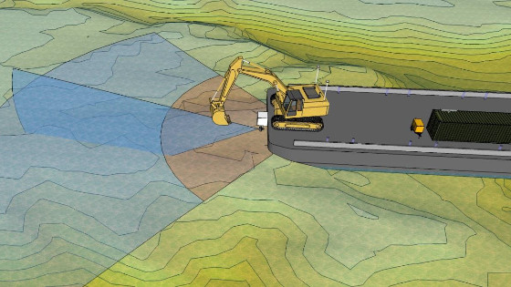
The system is part of the wirecrane/excavator installation. Figure 1 shows the layout of the equipment for a wirecrane. Standard equipment for the wirecrane are an RTK positioning system, heading, winch counters, boom angle sensor and a roll/pitch sensor. The data is interfaced in an interface box which sends the data to the computer via LAN. When the MotionScan sensor is added this data is also directly interfaced to the interface box. It is powered from the interface box as well.
The RTK position provides an accurate position and height which has an accuracy of about 2 cm. As the RTK height is so accurate it is used for tidal reduction. A draft sensor is not necessary anymore in this case.

Figure 1. Layout of the Equipment for wirecrane including motionscan sensor
The BV5000 is mounted on a pan/tilt unit. The pan/tilt unit can also rotate the system and is setup from the monitoring software. Figure 3 shows the area which is scanned. The BV5000 is mounted on the ponton viewing the working area of the dredge. The system is mounted to measure a vertical area and sweeps from left to right and back to cover the full seafloor.
The system can be set up to scan a sector with the multibeam and performs the scan automatically or manually.

Figure 2. Blue area is scanned with the Motionscan
The operation of the BV5000 is incorporated in the software. The set up is made as easy as possible so the operator can adjust the settings without interference of a hydrographic surveyor. Figure 3 shows the layout in the software and figure 4 shows the operation settings in more detail.

Figure 3. Picture of the equipment operation and software


Figure 4. Operation of the Motionscan sensor
During the dredge operation the DTM is updated for the position of the head. This is the standard Dredge Monitoring operation. After the area is dredged a scan is performed to show the latest situation.
Data from the scan is automatically cleaned for outliers and bad data. After the scan the new situation is shown in the DTM indicating whether the area fulfills the required depths. In this operation mode the scan is performed after the dredge cycle. The scan is carried out manually or at a certain interval. When material is spilled and therefor the area does not fulfill the required depths, it will show in the new DTM.
When the DTM from the MotionScan indicates the area fulfills the requirements, the dredge can move to a new location.

Figure 5. Insonification of the teeth of a bucket
A different operation mode is to scan the area continuously. The data points derived with the MotionScan are visible in the software together with the DTM. In figure 5 and 6 it is shown what the measurements look like. As the system scans continuously also the bucket is measured by the MotionScan. This shows the bucket in its environment which guides the dredge operator in hazardous areas. After an update of the DTM the data that measured the bucket are rejected and not used for the DTM. The updated DTM is used for further dredging or when the DTM indicates the area fulfills the requirements, the dredge can move to a new location.
3. Placing Material at a Required Position
For this project the dredge operator needed to place sandbags at a required position. The position of the grab is measured accurately with dredge monitoring software. The client used Teledyne PDS as monitoring software. The area is surveyed with a multibeam survey spread. But the real time situation can always change. Especially when material has to be placed near cables but it is not allowed to place or spoil material on top of the cables. A situation that occurs a lot nowadays near windfarm parks.
In this case a forward looking sonar is used to monitor the movements of the grab. Bags with sand had to be placed near a cable to protect is. The system was equipped with monitoring equipment but still it was important to see the real situation underwater. A camera is not possible due to the turbulence in the water. The solution was the forward looking sonar.

Figure 6. Top view of Data collected with the BV5000 combined with the DTM data
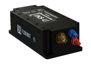
The Forward looking system including the pan/tilt unit is mounted on a pole on the pontoon. Figure 7 shows the mounting of the unit.

Figure 7. BlueView forward Looking system including Pan/tilt unit
It is mounted in such a way that it looks to the working area of the dredge. Figure 8 provides an example of the area covered by a forward looking system mounted on the pontoon. Instead of showing a point cloud of data points the forward looking system provides an image of the watercolumn. It shows not only the seafloor but also the items above the seafloor.

Figure 8. Example of Area covered with a forward looking system
The company used the system to place sandbags near a cable. In the image the objects have strong reflections. Behind the reflections a shadow is seen.
In figure 9 the grab with the bag and the forward looking image is shown.
In the forward looking image the cable to the windmill is clearly seen as well as the bags already place before and after the cable. The grab is clearly shown. When the reflection touches the shadow it placed at the seafloor.
This way it was quite easy for the operator to place the bags at the correct place. The image shows continuously the situation of the area. The accuracy of the position of the clamshell of a wirecrane is not very accurate. It is assumed that the clamshell is directly underneath the top of the boom. Movement of the clamshell caused by current or other forces is not measured. The grab is positioned in the area and shown in the software. The placement of the bags is monitored using the forward looking system once the grab is near the cable. The bags are placed relatively to the cable and previous laid sandbags.

Figure 9. Forward looking image of a grab with sandbag
4. Conclusion
Two methods are explained in this paper to provide tools for the dredge operator to monitor his work.
One method is the MotionScan which is a multibeam system with a pan/tilt unit mounted on the pontoon. The system is fully integrated in the dredge monitoring software. It can be performed in 2 ways: Continuously monitoring or scan after a dredge cycle. During the dredge operation the DTM is updated for the dredge movement. After a dredge cycle it scans the area and creates an updated Digital Terrain Model. The updated DTM indicates whether the area fulfills the requirements. The new DTM is automatically used for further dredging.
The second method is to use a forward looking system to place objects at the seafloor. The forward looking system is also mounted on a pole with a pan/tilt unit looking at the work area. It shows the objects in the full water column and is used to monitor the movement of the grab and its environment.
Both methods are used to monitor the operation and try to minimize the number of times a dredge vessel has to return to an area that was already dredged.
Do you have questions about this article?
Get in touch with Teledyne Marine, and they would be happy to answer any questions you have about pricing, suitability, availability, specs, etc.

More articles
