
How to Get the Best Precision and Improve Pointcloud Accuracy
We rarely stop to appreciate just how complex modern surveying technology is. Surveyors use the most advanced physics, with decades of experience, in every component. Consider how GPS uses timing calculations from atomic clocks and signals sent from orbit. This technology is now ubiquitous in everyday life. Or how LiDAR must make thousands of calculations a second regarding how long a light beam has taken to return to it. Consequently in such complex systems, there are many sources of error. Luckily however, we can talk about these quite broadly to better understand the accuracy of our surveying. This article will discuss further some important points for obtaining survey and pointcloud accuracy from a surveyor’s perspective.

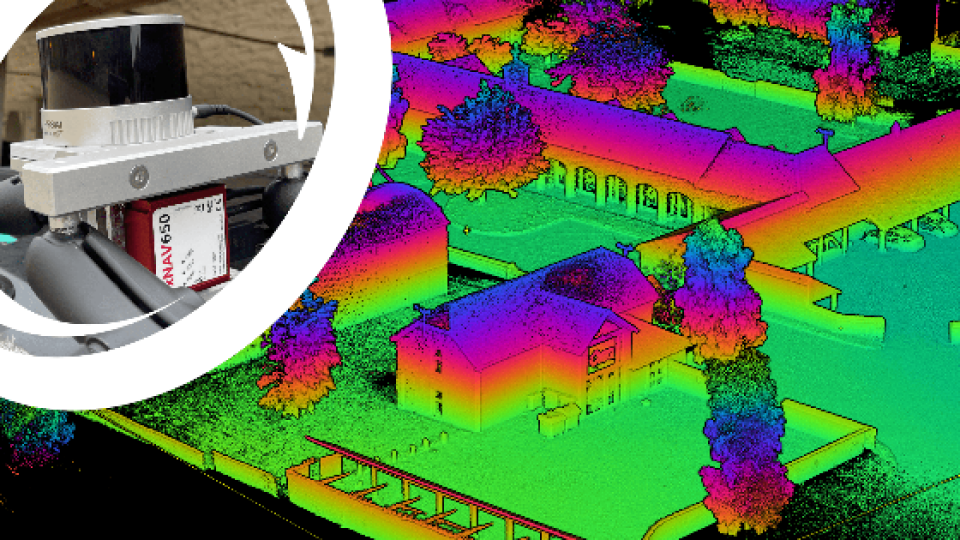
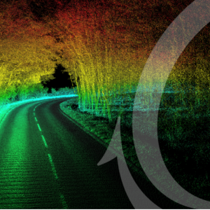
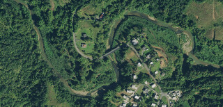
Pointcloud taken with a Hesai Pandar XT LiDAR and OxTS xNAV650 INS
IMU accuracy
An IMU (inertial measurement unit) measures the intrinsic movement to which it is subjected. Typically using gyroscopic instruments and accelerometers the IMU will determine its acceleration and changes in its orientation. For surveyors, therefore, an IMU is extremely important. This is because surveying typically is the observation of objects at a distance from oneself for the greatest convenience but the further away an object is, the less accurately its position can be known. Consider the diagram below; for all measurements, there is an intrinsic error including in the angle changes measured by the IMU.
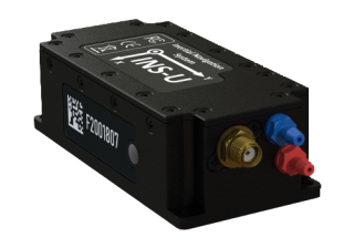
Taking a small angle approximation, the error in the position of an object is simply the angular error x distance to the object. This means that a tiny angular error can easily lead to a very large discrepancy in a surveyed object’s position by being at a long-range. A typical IMU for surveying such as the OxTS NAV650 IMU might have an accuracy of half a degree.

Position error in a survey due to orientation uncertainty
The IMU is also very important for navigation purposes. Intrinsically, the IMU measures motion. This means that surveyors can use it as a rudimentary navigation device to track how the IMU is moving. Therefore it is possible to use a high-grade IMU to output the essential orientation information but also the information of where the IMU is located. However, all instruments exhibit a random walk or adrift in their measurements that will negatively affect pointcloud accuracy. Therefore, an IMU alone will quickly drift away from its true position as it measures motion and does not localise position.
GNSS Localisation
A GNSS (global navigation satellite system) system localises its position on the Earth using the constellations of satellites in orbit. Using the highly accurate timing information from these satellite signals, a GNSS receiver is able to determine its position within much less than a meter on the Earth’s surface. By using a second receiver, often referred to as a base station, corrections can be calculated for how the signals from the satellites have been distorted in the atmosphere and this can increase the accuracy of the device to even a centimetre.
There are other systems that can be used for localising positions but most of them are limited to big infrastructure environments to act as a substitute when GNSS signals cannot be received, for now, there is no real competitor to GNSS in outdoors environments. GNSS gives highly accurate and precise absolute positioning on the Earth whereas many substitutes can only deliver relative positioning without the aid of GNSS itself.
GNSS Constellations
There are four main constellations of GNSS satellites in use today. For a long time the Russian and US constellations, GLONASS and GPS, have been ubiquitously used but the European and Chinese constellations, Galileo and Beidou, are becoming increasingly widespread also (there are others also, for example, QZSS). In general, accuracies using these individual constellations are similar, but a GNSS system can make the best use of all available data by using multiple, or all four, of these constellations combined. In the image shown below, you can see the trajectory of an INS system. The trajectory of a GPS only (blue) position trace and a GPS and GLONASS (red) trace is shown. As the vehicle has passed by some obstructive trees and buildings the satellite signals have been lost and position drift has occurred. In post-processing, this is seen by a sudden jump in the position of the blue line, and it appears to be moving in the wrong lane. However, in the red line, we see no such jump but a smooth trajectory in the correct place. This is because GNSS systems need a minimum number of satellites in order to provide optimal results. The more satellites or the more constellations, the more reliable the position output will be especially in poor GNSS environments such as a city or town. Nowadays systems such as the OxTS xNAV650 are moving towards offering all four of these constellations as standard for the most reliable solution.

GPS (blue) position trace and GPS+GLONASS (red)
Inertial Navigation Systems
A GNSS and an IMU system together play to each other’s strengths and weaknesses, making a complete navigation system. GNSS gives an accurate position of the system on the Earth and the IMU determines its orientation. Together the system delivers 3D position, highly accurate atomic clock timing from the GNSS and 3D orientation. This is often known as an INS (inertial navigation system).
The two streams of data can also be intelligently combined to give an even more accurate estimation of position and orientation, by continuously checking one data stream against the other. For example, when there are obstructions to the satellite signals the GNSS data can exhibit large errors in its position output but by comparing this to the accelerometer data an INS can determine the most plausible trajectory. In such times, or when there is no view at all of satellite signals, the IMU’s measured accelerations can be used to estimate the trajectory of the device. This will not be nearly as accurate as when GNSS is used but it does make a decent stopgap for such situations.

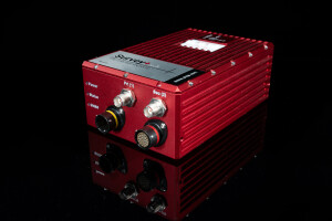
xNAV650 INS and Hesai XT LiDAR mounted on a car for mobile mapping
An OxTS INS for example might exhibit about one metre of drift in a full minute without GNSS updates. When GNSS is regained, the true position is used and the data captured can be improved in post-processing to get a realistic trajectory.
Other instruments can also be incorporated and their data streams used to check others. For example, a wheel-speed sensor is commonly used in mobile mapping applications. This device simply measures the movement of the wheels on a vehicle to get another reading of where the vehicle might be. In this case, a pseudo-speed is measured. This data stream, like the IMU, is available even when GNSS signals are not and so it can make a very useful addition in poor GNSS conditions such as forests or urban areas where signals can be obstructed or distorted. In the comparison pictures below, a stretch of a neighbourhood has had GNSS signals artificially blocked completely.

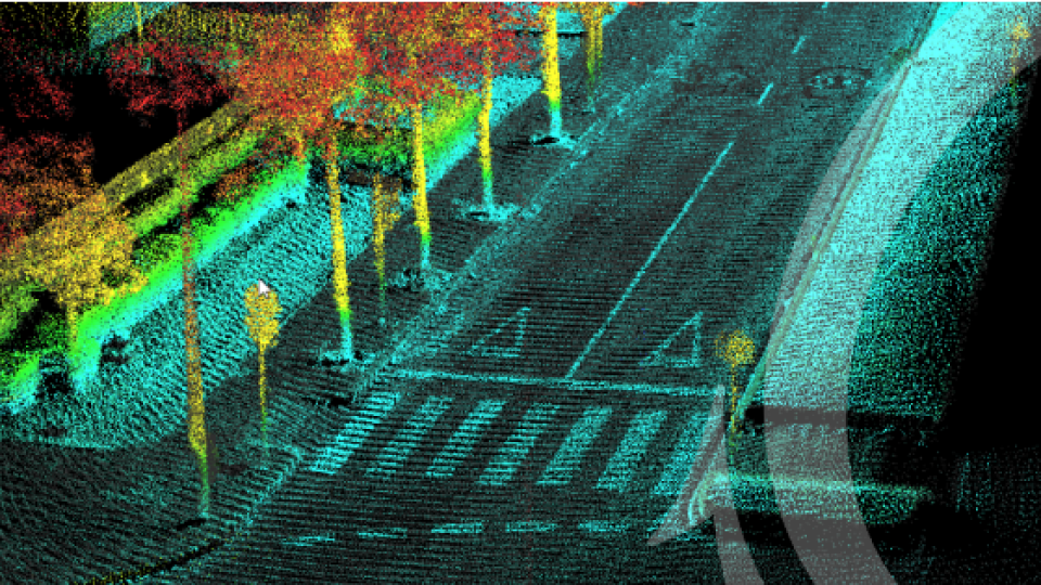
A survey of a neighbourhood section with no GNSS, coloured by point position uncertainty

The same survey but now making use of wheelspeed data
The colours in the pointcloud are estimates of uncertainty with blue being the highest accuracy, then dark then light greens, yellow, orange being representative of poorer accuracy and red the lowest with a large amount of drift. In the first picture, you can see that most of the survey is red, meaning it is poor accuracy, getting up to half a meter in point position uncertainty. However, the second picture which used the same process but with a wheel-speed sensor in addition, shows a larger percentage of surveying achieved the highest level of accuracy. Looking close up, substantial improvements can be seen as the wheel-speed prevents shift in parts of the pointcloud by almost half a metre with considerably less blurring. This makes a wheel-speed sensor a great addition to mobile mapping setups in such environments.
Boresight Calibration
As we mentioned before, surveying data is highly sensitive to orientation data because of its propagation over distance. But there is another source of orientation error which is between the IMU and the surveying device. In order to combine, or georeference, navigation data from an INS and surveying data, say from a LiDAR, the spatial relationship between the two must be known. The displacements and rotations along each 3D axis must be measured. And this orientation error will contribute to the position error of points. This error is referred to as a boresight misalignment.
Unfortunately, it can be very difficult to measure these angles to the degree of accuracy necessary for survey-grade data. Several methods might be used, for example, using a CAD printed mount to tightly bind the INS and Lidar together at a known orientation and displacement, but recall that accuracies must be of the order of half a degree or better. Another method, one developed by OxTS, is to use a data-driven technique to calibrate the angles. This has several benefits including being done entirely by software and taking only ten minutes.

Hardware setup view in OxTS Georeferencer
In the diagram below, you can see the importance of getting your orientation angles as accurate as possible. Viewed at a distance from different perspectives, objects will appear in the wrong place and they will start to blur, especially when frames are combined together in a pointcloud. Unfortunately, surveyors are not able to simply secure their devices to a vehicle and survey without carefully measuring the relation between INS and LiDAR, that is, without a data-driven calibration technique that requires only that the devices are rigidly mounted together. By performing a short survey of some reflective targets, OxTS Georeferencer is able to calibrate the relative orientation to points of a degree.

Diagram of the effect of a boresight misalignment
Accuracy calculation
Using the IMU and GNSS data, the INS is able to calculate a large range of diagnostic information and to estimate the uncertainties at which is it outputting data. This information can be extremely powerful for surveyors. OxTS uses a formula that combines the accuracy specification of common LiDAR and the accuracies reported by the INS to calculate an estimate of the uncertainty in the positions of all points of a pointcloud. This is automatically generated when using OxTS Georeferencer and fills a scalar field of values so that the data can be viewed and analysed in pointcloud viewing software. This allows users to see exactly where they might need to resurvey. By seeing orange or red points, an area might be identified where the methodology of surveying could be improved.
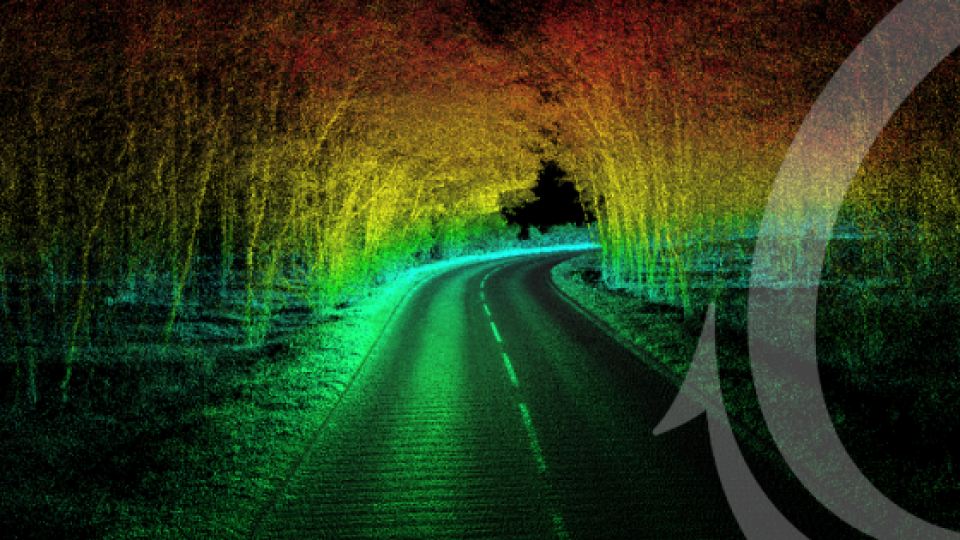
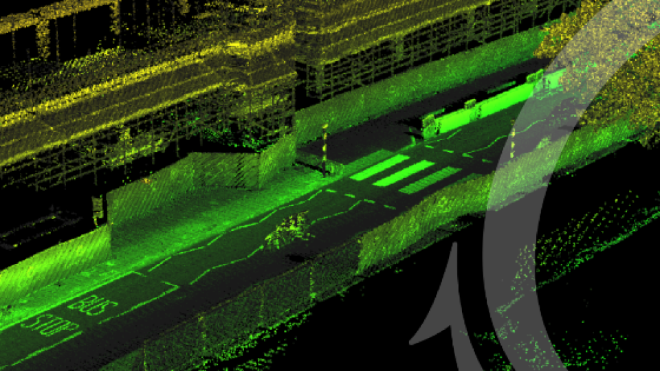
For example, consider the Road Survey shown below. When the vehicle moved under the tree line and satellite signals began to be lost, the INS position started to drift resulting in lighter green, then yellow and orange points as it regained GNSS view. The surveyor might decide that this is an important area and it needs resurveying. The survey could be simply improved by driving the vehicle in the opposite direction down the road so that the survey has high accuracy points on that area.
Alternatively, or in addition, the surveyor could decide to simply remove the inaccurate points. Since these values are stored in a scalar field, like GPS time or intensity, they can be easily removed in any pointcloud viewing software or in OxTS Georeferencer itself. OxTS Georeferencer gives users the ability to choose an exact position uncertainty not to process points under. For example, if you only wanted points known to five centimetres or better. This can only ever be an estimate and the specific LiDAR type and/or errors in hardware setup would be additional factors.

Pointcloud coloured by OxTS’ uncertainty estimation
In the example above, shown for the wheel-speed sensor, we saw how this feature can be used to compare the accuracy of surveys. It could also be used proactively to remove the inaccurate points. For example, you could remove all of the least accurate, red points and leave only the green and blue. This would mean that an area without GNSS will have almost no survey-grade data but with a wheel-speed, much of the area can maintain the high accuracy required and with several passes most of the survey will be maintained.
In conclusion
We have identified the contributions to the final errors in point positions from a number of sources and some ways to combat these. In particular, we have seen that survey data is very sensitive to angular errors when surveying over a long-range which makes the IMU specification and reliability very important and also the measured relations between surveying equipment. No matter how much consideration we make into reducing these contributions, there will always be some residual error. That is why it is a good idea to make use of the information we have to estimate and analyse the errors throughout a survey to understand where might need extra attention. Furthermore, this can be used to automatically improve the final data by including only points taken in the most optimal conditions.
Jacob Amacker
Product Engineer, OxTS
Do you have questions about this article?
Get in touch with Oxford Technical Solutions - OxTS, and they would be happy to answer any questions you have about pricing, suitability, availability, specs, etc.


