High-precision Mobile and Airborne Survey
Relying on a consolidated experience in the field of mapping and surveying, road asset and facility management, and powered by a forward-leaning attitude, Siteco develops and sells world-class technology Mobile Mapping Systems. The Road-Scanner project started with the collaboration of the universities of Parma and Bologna.
Amberg Technologies, an international leading provider of specialized system solutions for the construction and monitoring of civil infrastructures, assigned to Siteco a survey of a stretch of 15 km of the A2 motorway, from Biasca to Faido. The aim of the project was verifying the quality of the data surveyed with RoadScanner and the creation of a database of the roadside assets. A specific area of investigation of about 2,1 km was prepared within the stretch, in order to check accuracy and reliability of the MMS survey. In this particular area a topographic high-precision survey was carried out, through a polygonal, by surveying 9 control points for each carriageway. These points made it possible to check the accuracy of the data produced with the mobile survey. In the same area, a Lidar survey was executed with a helicopter, providing a further source of data for the check.
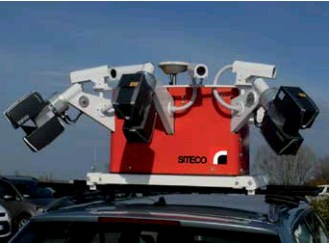
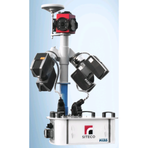
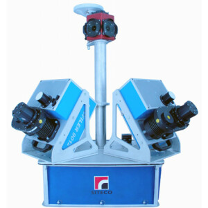
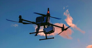
Fig. 1: The Road-Scanner3 Mobile Mapping System
Methodology
he topographic polygonal was obtained by defining the vertices with targets and using some external reattachment points. The topographic targets were installed on the guard-rail and on the border of the motorway pavement so as to be clearly visible, and easy to collimate using the photogrammetric software Road-SIT Survey that allows the operator to intervene directly on the videos and on the point clouds surveyed with Road-Scanner. The equipment used for this survey consisted in 3 Faro Focus 3D laser scanners and 7 high-definition cameras (4 Mpx). With this equipment it was possible to obtain a network of laser points with a maximum distance between the points of about 5 cm and a full high-quality view of the infrastructure.
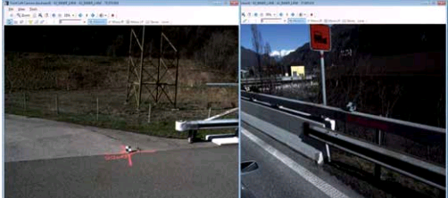
Fig. 2: Ground control points
Accuracy obtained:
The comparison between the coordinates of the targets obtained with the MMS survey and the coordinates defined with the topographic polygonal, showed very limited deviations, within 2.4 cm for most of the points. In 6 cases the deviation was higher, but in any case within 3.4 cm. These values were compatible with the required tolerance, thus no operation of clearing or adaptation of the trajectories was necessary. To be noted that the Road-SIT package contains specific functions for the “rectification” of the trajectory of the vehicle based on the control points. This process uses statistical analyses of the deviations and provides the recalculation of the coordinates of videos and point clouds.
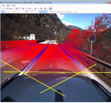
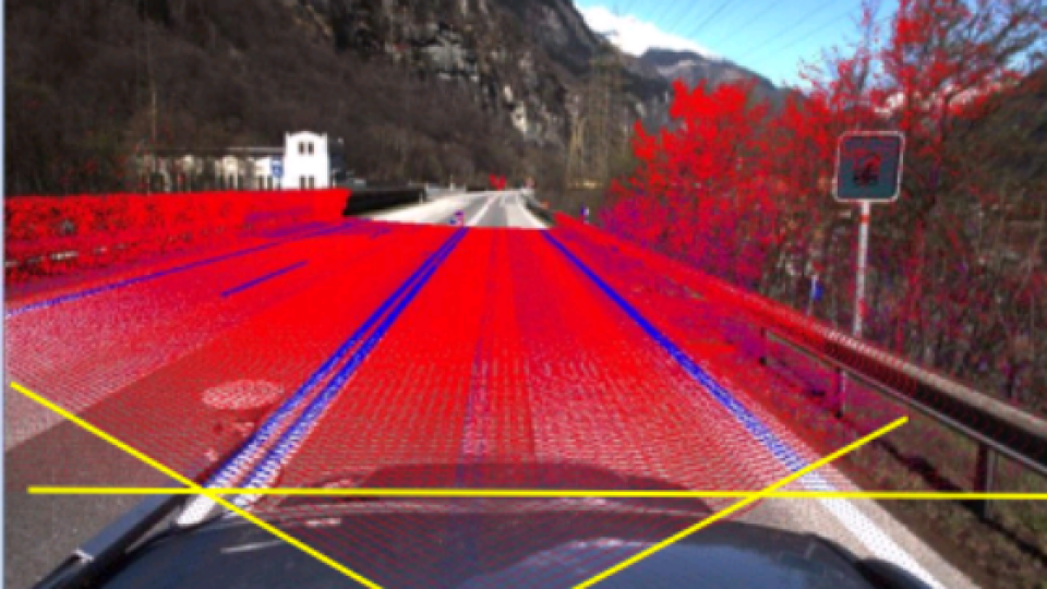
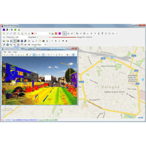
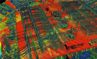
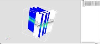
Fig. 3: The yellow lines in the image above represent the planes of the scans of the 3 laser scanners mounted on the vehicle. The color of the clouds of points, on the basis of the reflectance, allows the highlight of the markings.
The yellow lines in the image above represent the planes of the scans of the 3 laser scanners mounted on the vehicle. The color of the clouds of points, on the basis of the reflectance, allows the highlight of the markings.
Digitization of the survey data
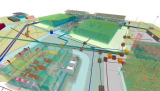
The digitization of the key information that characterizes the motorway was carried out with the tools of the software package Road-SIT Survey. These data were exported to a CAD format and displayed overlapped to the videos. The 3D view made it easier to consult the information collected and get an overview of the infrastructure.
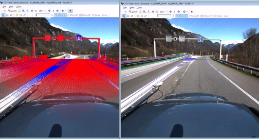
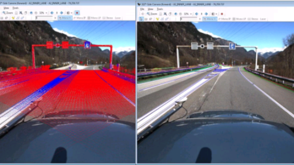
Fig. 4: The Road-SIT Survey application
The Road-SIT Survey application allows also the creation of sections based on a line entered by the user, i.e. with a generic (longitudinal, cross, or slant) orientation. These sections are very useful in the process of digitizing the road data.
Overlapping of the MMS survey to the Lidar survey with helicopter
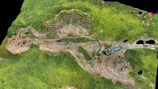
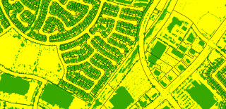
After the mobile survey completion, a Lidar survey with a helicopter was carried out on the same stretch of motorway, obviously keeping the same reference system. The data obtained with the two surveys were exported to the standard LAS format and displayed in overlapping. The density of the points outside the carriageway is much more reduced because these points were acquired only with the helicopter. On the motorway, instead, both land and airborne surveys are present and perfectly overlapped. To be noted that the MMS scans density is 100 times higher than that of the helicopter. The deviation between the two surveys is very limited, within 2-3 cm for 90% of the points. By analyzing a point cloud section, it is possible to appreciate the level of correspondence between the two surveys. This result had already been found during the testing with the topographic survey of the control points. The integration of the two surveys provides a complete view of the road infrastructure, combining the benefits of the two different techniques of acquisition:
• The Lidar approach that assures a wide-range survey with a level of details sufficient to recognize the road assets (slopes, embankments, water crossings and pipelines, etc.)
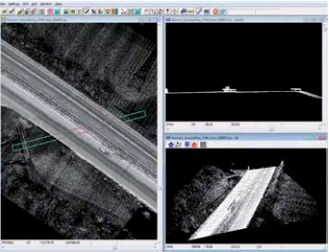
Fig. 5: overlapping of mobile and airborne survey.
• The MMS survey which provides very detailed information on the road with precision measurements for the single objects. The road survey allows also an optimal view for the acquisition of the information on signage, advertising plants and the overall street furniture. and the definition of a digital terrain model;


