Get the Best out of your INS-Lidar System with Data-Driven Boresight Calibration using OxTS Georeferencer
The OxTS Boresight Calibration feature allows you to get the very best data out of an INS-Lidar system and to get precision that is not possible without a data-driven approach. The calibration procedure can be added onto a survey run without hassle in 5 minutes and the work is done by the OxTS Georeferencer software.
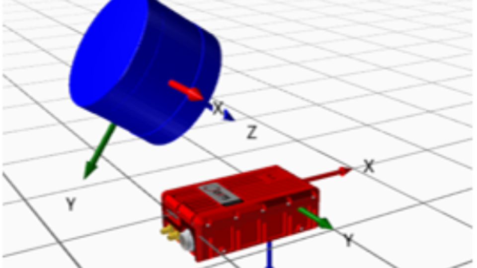
Align your tracking device (INS) and your surveying device (Lidar)
A boresight misalignment occurs when there is an imprecision in the angles measured between your tracking device (INS) and your surveying device (Lidar). Small errors in your heading, pitch and roll angles are often unimportant when you are only considering your position but when you are surveying objects some 10-100 meters away a tiny angular imprecision causes significant if not fatal distortions in your data.
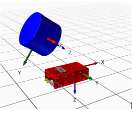
It is, therefore, crucial to measure these angles as precisely as possible (to around 0.1°) and this is often impossible by eye or using physical measuring devices, what is needed then is a data-driven calibration technique and this is what OxTS provides.
Why is the misalignment between your inertial navigation systems (INS) and your surveying device (Lidar) a problem?
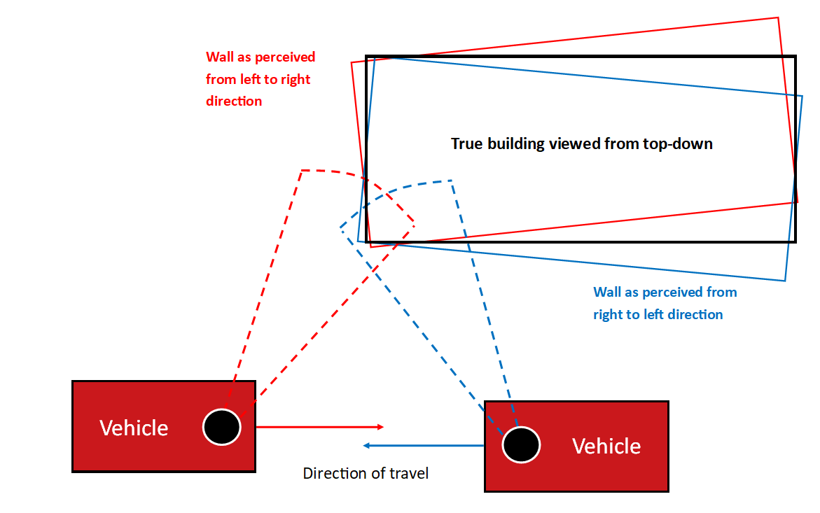
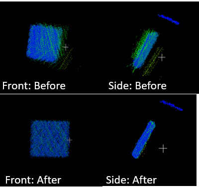
When you try to view an object (the black rectangle) it will have a position and orientation-dependent on where you are viewing it from. It will appear displaced and distorted. When you survey the same object from several directions you get a blurring effect. This will make distance and volume measurements inaccurate and in the worst case impossible.
As a quick calculation, if you have an error in one axis of just 0.2° then for a point 10m away there will be a position error of approximately 0.2 ×2360×2π×10≃7cm .
.
Some example data:
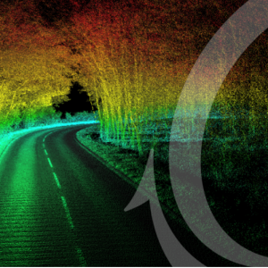
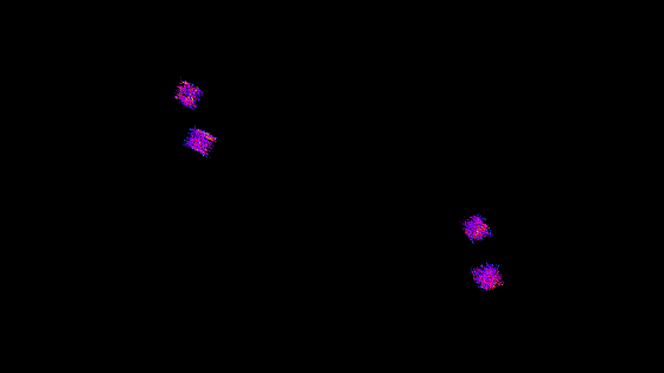
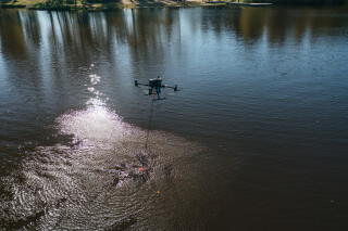
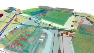
The following is a user’s data taken by a UAV at about 50m of altitude using an xNAV550 and a VLP16 Lidar.
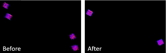
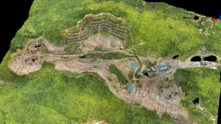
The two square targets you can see looked like four targets without performing the calibration. Afterwards, the targets are firmly aligned on top of each other as they should be and they are also crisper and more square.
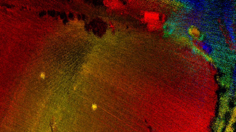
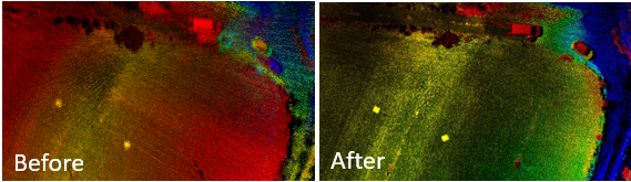
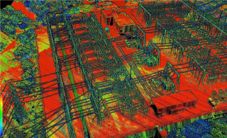
Below is the same data but with the full point cloud, not just the targets. The data becomes much more clear and usable. What looks like two cars becomes one and other features are now identifiable.
Below is another example of data fixed by a boresight calibration. The targets have been shifted by about 80cm giving a very inaccurate point cloud before calibrating but afterwards, the data is perfect.
The angles were measured by eye, to begin with to 90°, 0° and 55° on the three axes. The boresight calibration corrected these to 88.74°, -0.43° and 54.86°. These small-angle corrections have made a huge impact and they can only be made using a data-driven calibration technique.
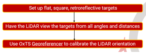
What is the procedure?
The procedure is very simple. Set up some flat, square retroreflective targets (these can be made simpler with a wooden board and some cheap retroreflective tape. Set up your Lidar and INS device and configure them to start surveying, measuring the position and orientation of the LiDAR relative to the INS. Manoeuvre your vehicle in such a way that the Lidar device sees the targets from as many distances and angles as possible. This shouldn’t take more than 5 minutes, after which you can immediately begin your survey without restarting any systems. Later on, when you are processing your data you follow the simple boresighting instructions in the OxTS Georeferencer software and your data will be calibrated.
The boresighting calibration feature that we offer will allow you to get the best data possible out of your setup and it will only have to be done once if you do not change your setup.
Do you have questions about this case study?
Get in touch with Oxford Technical Solutions - OxTS, and they would be happy to answer any questions you have about pricing, suitability, availability, specs, etc.

Related products
