Airborne Laser Scanning with UAVs - Understanding The Key Factors to Generate Highest Grade LIDAR Point Clouds
In this white paper, Aeroscout presents the key factors to generate highest grade LIDAR point clouds recorded by an UAV (Unmanned Aerial Vehicle). Some typical mission scenarios are given in the beginning. Common limitations of the UAV are discussed in detail and possibilities to increase the quality of the data are summarized. Finally, important factors of the two special cases called power line corridor scanning and forest scanning are given and a checklist to test an UAV for its LIDAR capabilities is provided.
1. INTRODUCTION
LIDAR with UAV is possible since about ten years. The downsizing of the components on the one side and the developments of the carrier platforms (UAVs) on the other side made it possible to use these systems for various kind of applications. Read on to understand the strong connection between the onboard sensors and UAV itself, which can lead to highest grade LIDAR point clouds in an optimal case.
2. MISSION SCENARIO
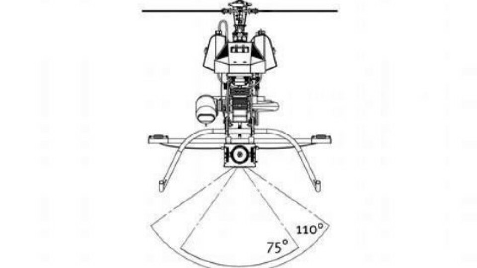
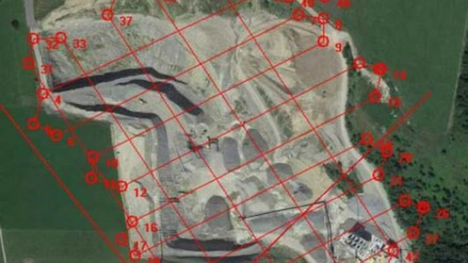
Today's laser scanner, designed for UAVs like the Riegl VUX-1 UAV [1], have a measurement rate up to 500`000 meas./sec. Reduced to a typical usable field of view (FOV, Fig. 1) of 110°, this results in 166'000 meas/sec. This sounds like a lot but is it? It strongly depends on the application and how the requirement on point density is defined. Due to the slow airspeed, UAVs are typically used on relatively small areas compared to manned aircrafts i.e. in the square kilometer range. But, a much higher point density is most of the time desired instead. More than 100 points/m2 is the typical minimum and it can go up to 2000 point/m2. Fig. 2 shows a flight plan for a open-pit mine. As common for airborne airborne laser scanning with manned aircrafts, the stripes are planned in parallel with an overlapping factor to match the scan lines in post-processing to each other and increase the accuracy. To get a better coverage, a second batch of scan lines are planed perpendicular to the first one.

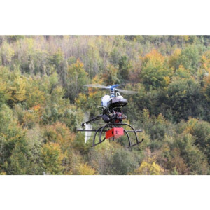
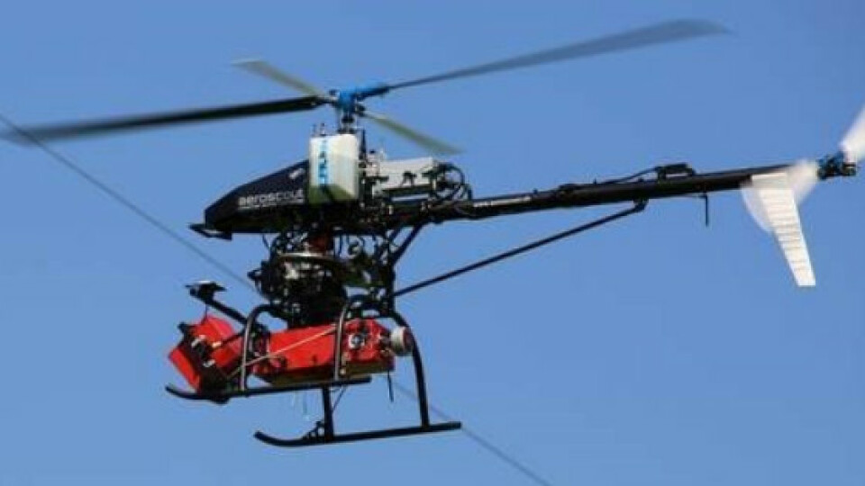
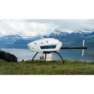
Fig. 1: The Laser payload is mounted perpendicular to the flight direction of the UAV (Aeroscout Scout B1-100 [2]). Two typical scanning opening angle for flat areas are shown

Fig. 2: Mission planing of a open-pit mine scan with 850 points/m2 [3]Table I shows three scenarios to describe the mapping possibilities of one hour scanning time with the Riegl VUX-1 UAV laser scanner.
TABLE I
|
Scenario |
1 |
2 |
3 |
|
Area covered [km2] |
1 |
6 |
10 |
|
Flight velocity [m/s] |
5 |
10 |
15 |
|
Flight altitude [m AGL] |
50 |
80 |
100 |
|
Scanning angle [deg] |
75 |
110 |
110 |
|
Point to point distance [cm] |
6 |
10 |
15 |
|
Line to line distance [cm] |
6 |
10 |
15 |
|
Points density [pts/m2] |
300 |
100 |
50 |
|
Scan duration [min] |
60 |
60 |
60 |
|
Data size [GB] |
8 |
12 |
12 |
3. GPS/INS UNIT
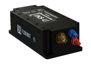
Beside the laser scanner itself, the payload is also consisting of a high grade GPS/INS unit (Global Positioning System/ Inertial Navigation System) to calculate the exact position and attitude of the laser scanner at the time when the laser beam measures the distance to ground. The INS itself consists of accelerometers and gyroscopes, combined in the IMU ( Inertial Measurement Unit) which has to be tightly coupled to the laser scanner.
4. SCANNING TIME VS. FLIGHT TIME
The application examples in Table I show the true scanning time (60min) but not the true flight time. Depending on the scenario, a typical 10% overhead has to be added to the scanning time to account for turns and other maneuvers outside of the scanning lines. Additionally, there is a takeoff and landing phase and the distance/altitude difference from the takeoff location to the mission area. It is important to know that the flight path to the scanning area should not be a direct line but should contain dynamic maneuvers like S-curves. This is because the GPS/INS uses a initialization algorithm to bring its position and attitude to the highest possible precision. It has to be performed before scanning and ideally also after scanning. Table II shows the typical duration for this maneuvers.
TABLE 2
|
Warm-up |
0-3 min |
|
Takeoff |
1 min |
|
Climb to mission area & INS swing-in |
2-5 min |
|
Turns and maneuvers during scanning |
10% scan time |
|
Return to home & INS swing-in |
2-5 min |
|
Fuel quantity left |
10 min |
|
Battery power left (for e-engine UAVs) |
3-5 min |
|
Landing |
1 min |
As a result, if a drone has a maximum flight time of 30min, it can only do a 20min scan in the best case and a 15min scan in a worse case. If the UAV has to scan 1km2 at 300pts/m2 it needs 3-4 flights. If it has a 90min endurance it can do at least a 60min scan flight and cover the whole area in once.
5. STABILITY IN THE AIR
The experience has shown that the stability of the UAV during the scanning mission strongly correlates with the data quality of the point cloud. The laser scanner uses a rotating mirror to create a scan line perpendicular to the flight path. First, a uniform spacing of the scan lines can only be achieved by the stable attitude behavior of the UAV's pitch axis. Second, a wide scan angle, e.g. 110° or more, make a stable yaw axis (vertical axis) even more important to avoid overlapping scan lines at the outer points. Additionally, GPS/INS position and attitude errors have greater influence on the data during unstable flight behavior and are very hard to correct.

Fig. 3: Laser point cloud generated onboard of an UAV with bad attitude behavior. This effect increases with windy conditions.
The following features tend to increase the attitude stability of an rotary UAV (especially in windy conditions and in forward flight)
- Higher gross takeoff weight
- Higher tip speed of the rotor
- Minimum number of propellers / rotors / rotor blades
- Smaller cross section / aerodynamic shape
- Higher mass of rotor blades
- Higher disk loading (rotor area/weight)
- Decoupled control axes e.g. separate tail rotor
- High grade autopilot unit
- Autopilot specially tuned for LIDAR
Another important option is to decouple the payload (laser scanner + GPS/INS unit) from the airframe by large low frequency dampers. However, this is typically just an option for bigger UAV due to payload weight constraints. The analysis of the laser flight trajectory compared to the trajectory generated by the autopilot shows that vertical wind gusts which disturbing the pitch stability of the UAV, but also horizontal wind gusts disturbing the yaw stability can be damped out to a certain degree by decoupling the payload.

Fig. 4: Low frequency dampers to decouple the airframe from theLIDAR payload.
6. VIBRATION LEVEL ON THE PAYLOAD COMPONENTS
The precision of the INS depends strongly on the vibration level at which the sensor is exposed to. The amplitude of the acceleration on the airframe of an UAV can easily exceed 10g. Normally this is no problem for the components unless it is a highest grade IMU or laser scanner. On a rotary wing aircraft, not only the engine is generating vibrations but also the rotors. Even with perfect weight balancing, a rotor will always generate vibrations due to the asymmetrical inflow in forward flight. The impact of vibrations on the IMU is often not directly visible in the data. Only after combining the trajectory with the LIDAR data, the error becomes obvious. It is not possible to combine the stripes on every location in the point cloud. Major differences will remain and can not be corrected by the software algorithms (Fig. 5).

Fig. 5: Different scan lines which do not fit after post processing of the point cloud due to vibration disturbed IMU sensor unit.
7. UAV KEY FACTORS FOR SPECIAL CASES
The downsizing of laser scanner and INS systems in the last years opened the possibility to use the free payload capacity of the UAV system for combined sensor payloads. The inspection of power lines for example is very cost sensitive [5]. Typically, power lines have to be inspected along several 10-100 kilometers. Only a long endurance UAV with enough load capacity for a multi sensor payload composed of a laser scanner, a daylight camera and a corona camera combined in one payload can do this job efficiently.
Beside the main components, an additional weight overhead has to be added in for housing, cabling, power converter, batteries, wireless data links and data storage units.
Further, power line inspection needs a faster forward flight speed and a good efficiency of the UAV at this speed to keep the costs low. The laser scan corridor consist only of one stripe to save the time for the way back. This means that the laser scanner and the GPS/INS system have to be high grade components because the matching of overlapping scan lines for an increased accuracy is not possible in this case.

Fig. 6: Multi sensor payload for power line inspection including a VUX-1 laser scanner, daylight camera, corona camera and HD-video stream mounted on a Scout B1-100 UAV helicopter [5]
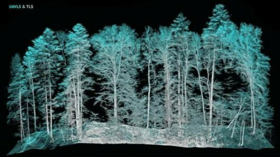
Another special case for laser scanning are forest areas. Today's software tools can generate a lot of valuable information from ultra high density point clouds. The precondition is to have a density of 2000 points/m2 or more and an accuracy of < 2cm RMSE on flat ground [6]. The total scan time for this type of application is typically several hours and need a long endurance UAV. Often, the UAV has to operate far away from the ground control station because the mission area has no open space to takeoff or to guarantee direct line of sight to the operators. All components have to operate at its maximal possible specifications for this most challenging application.

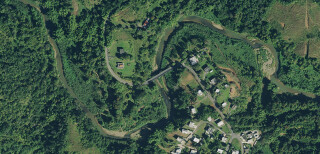
Fig. 7: Section view to compare the airborne laser scan recorded by the UAV to the terrestrial laser scan. [7] The necessary flights were performed by Aeroscout.
8. CONCLUSION
This paper presented the most important key factors to generate highest grade LIDAR point clouds from over ten years of experience in various projects around the globe. There is clearly a difference between a well flying UAV and an UAV suitable for airborne laser scanning. Aeroscout was a pioneer in this field and was probably the first company which integrated a laser scanner (Riegl LMS-Q160) on an UAV as a contributor to the EU research project [8] “BACS” at ETH Zurich (20062010). Since then, Aeroscout continued the development of successful airborne laser scanning with UAVs under the name “ALMI Technology”. A close relationship to Riegl as producer of laser scanners was crucial to develop an unmanned system where the scanner and the GPS/INS sensors work hand in hand with the UAV helicopter as a carrier platform. Aeroscout uses its knowledge not only to offer services for highest requirement projects but also to train the customer flight crews after the purchase of an UAV system for airborne laser scanning.
9. CHECKLIST UAVS FOR LIDAR
Unfortunately, with the growing popularity of LIDAR with UAV systems, the market offers shady companies which are providing systems for airborne laser scanning without any knowledge on this topic nor any good data record from their own system. Aeroscout recommends to discuss at least the following points with the potential provider of a service or an UAS system in a early stage:
-
Ask for a reference data set similar to the desired application. Consider environmental factors like wind, temperature, humidity, special topology, altitude and accessibility to the scanning area.
- Ask for raw data of a reference project i.e. the flight trajectory and the lidar data from the laser scanner an process the data by yourself if you have the software tools or contact a processing company.
- Let you demonstrate the stated endurance of the UAV on a similar mission profile as you plan and with the needed payload capacity.
- Consider the maximum payload for your application including additional components. Consider also the free payload margin for an upgrade with an additional camera or sensors.
10. REFERENCES
-
Riegl, VUX-1 UAV datasheet, 2017
- Aeroscout, Scout B1-100 UAV Helicopter datasheet, 2016, https://www.aeroscout.ch/index.php/scout-uav-helicopters/scout-b1-
- Aeroscout, Demonstration of Airborne Laser Scanning with theScout B1-100 UAV Helicopter and the Riegl VQ 480-U, 2014
- Aeroscout, ALMI Technology Brochure, 2015,
https://www.aeroscout.ch/index.php/airborne-laser-scanning [5] Hochschule Luzern, EWZ, Aeroscout, KTI Research Project Nr. 18131.1 PFIW IW, 2017, https://www.kti.admin.ch/kti/en/home.html [6] J. Kellner, GEDI Project internal report, November 2017, https://science.nasa.gov/missions/gedi
[7] F. Morsdorf, UAV-based LiDAR acquisition for the derivation of high-resolution forest and ground information, July 2017, Paper THE
LEADING EDGE,
https://library.seg.org/doi/abs/10.1190/tle36070566.1 [8] BACS FP6-IST-027140, 2006-2010
Published by
Aeroscout GmbH
Technikumstrasse 21
6048 Horw
Switzerland
© Aeroscout GmbH All Rights Reserved
Please note:
THIS DOCUMENT IS FOR INFORMATION PURPOSES ONLY AND ANY INFORMATION GIVEN HEREIN SHALL IN NO EVENT BE REGARDED AS A WARRANTY, GUARANTEE OR DESCRIPTION OF ANY FUNCTIONALITY, CONDITIONS AND/OR QUALITY OF OUR PRODUCTS OR ANY SUITABILITY FOR A PARTICULAR PURPOSE. WITH REGARD TO THE TECHNICAL SPECIFICATIONS OF OUR PRODUCTS , WE KINDLY ASK YOU TO REFER TO THE RELEVANT PRODUCT DATA SHEETS PROVIDED BY US. OUR CUSTOMERS AND THEIR TECHNICAL DEPARTMENTS ARE REQUIRED TO EVALUATE THE SUITABILITY OF OUR PRODUCTS FOR THE INTENDED APPLICATION .
WE RESERVE THE RIGHT TO CHANGE THIS DOCUMENT AND/OR THE INFORMATION GIVEN HEREIN AT ANY TIME.
Additional information
For further information on technologies, our products, the application of our products, delivery terms and conditions and/or prices please contact Aeroscout (www.aeroscout.swiss, [email protected])


