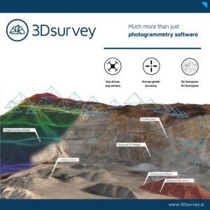
TcpMDT Standard
Surveys, digital terrain model, contours, profiles and volumes
MDT is an application that is installed as a plugin on AutoCAD, BricsCAD, GStarCAD or ZWCAD. It offers a powerful set of tools for easy learning and has a modular structure. The standard version allows you to model a terrain using points measured by any total station or GPS, generate contours, derive longitudinal and transversal profiles, calculate volumes and visualise the terrain in 3D. It also has functions to work with plots and multiple additional utilities.
APLITOP
Málaga, ES
Description
Introduction
MDT is an application that is installed as a plugin on AutoCAD, BricsCAD, GStarCAD or ZWCAD. It offers a powerful set of tools for easy learning and has a modular structure.It shows great versatility through the import and export of files in the most common formats, such as LandXML, DWG and many more.
Topographic Points
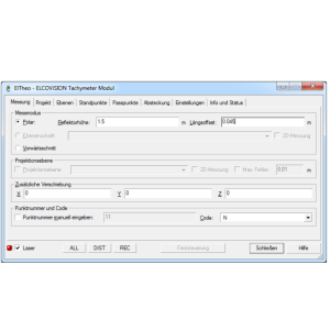
The program starts to run from coordinates obtained by total stations or GNSS receivers, converting files from field applications. If TcpET or TcpGPS has been used, in addition to the coordinates, the raw data of the observations are imported, as well as the linked photographs and voice notes.It is also possible to create new points from CAD entities drawn by other programs.If codes have been assigned to points in the field, the program will automatically draw the planimetry and blocks defined by the user.In addition, we can run all kinds of editing and filtering operations.
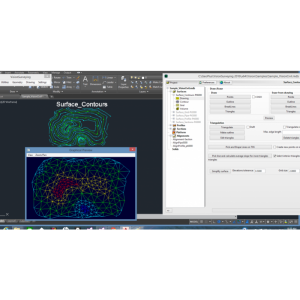
Surfaces
Break lines can be defined graphically, by sequence of points, codes or by importing files. Triangulation can be created from points, with or without break lines and by applying angle or maximum length controls. There are also options for flat triangles minimization and automatic gap repair. There are commands for interactive editing of the surface, and it also offers tools to detect and repair errors.
Contours Lines
MDT can generate contour lines with an interval or at special elevations and they are updated automatically with each change in triangulation.The contours can be labelled manually or automatically with style, size and layer personalization. Another command allows additional labels to be placed anywhere on the surface.
There are also other commands for interpolating, breaking and joining curves, adding vertices, editing curves, discretizing polylines and splines, detecting elevation errors etc. Other tools make it possible to import files in shape and other formats.
Meshes
Meshes may be created from a surface, contours, 3D entities or mesh files in various known formats (Arc/Info, LAS, GeoTIFF, etc.). It also has commands for mesh processing such as joins, filtering and resampling, conversions etc.They may be represented as 3D faces, polyface mesh or image, all being suitable for export to realism and animation programs.
Profiles
The profiles may be calculated based on a surface, 3D cartography or by regression from points near the alignment. The quick profile command allows the user to draw a line on the surface and quickly show the profile.The profiles may be updated automatically when the original alignment or surface have changed. Furthermore, it has a powerful CAD independent profile editor which allows graphic and numerical editing. The drawing is fully customizable, including the use of paper space or model, sheet templates, style, justification and text sizes.
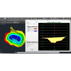
Cross Sections
The terrain cross sections may also be obtained from points, a surface or mesh, 3D cartography or by the conversion of files from the most usual formats. The drawing is highly customizable in such a way that we can decide on those elements which must be labelled.It is also possible to insert blocks and project 3D polylines on the profiles.
MDT allows users to draw several profiles simultaneously to see different layers or stages of evolution of the project. A powerful editor allows the profiles to be graphically modified by moving the vertices or numerically by modifying distances or elevations. If the original surface or alignment are modified, the profiles may be automatically updated.
Volumes
Cut and fill volumes can be calculated from a comparison between meshes, surfaces or cross sections. The results of meshes and surfaces are represented by areas using color palettes, with a customizable legend and interval.
Images
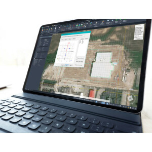
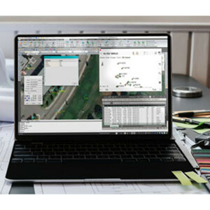
MDT has commands for inserting georeferenced images and orthophotos in their real position on the terrain and assigning them to a surface or assigning predefined textures to surfaces, and place photos with position at their real location on the map.It also allows access to the web map services (WMS, WMTS) provided by public and private entities in such a way that the user must only specify a window, choose the service and the program will automatically insert the image in the right place on the drawing. Another utility enables the user to export points, surface and layers of the drawing to Google Earth.
Maps
MDT can draw a 3-D mesh based on contours or surface and maps of heights, slopes, orientations or visibility from a point can be generated.It includes a powerful terrain viewer in which the lighting conditions can be changed and simulate phenomena such as fog, rain, wind, etc.It includes a ready-to-use library of textures to apply to models, and another of 3D objects with trees, vegetation, rocks, signs, street furniture, etc. useful to enhance presentations. Another interesting feature is the total immersion in the field through Virtual Reality technology, using Oculus Rift headset and moving freely with the X-Box gamepad.
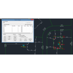
Plots
This menu includes options for creating and editing plots and buildings. It also has tools for plot division by area, parallel and perpendicular to one side, azimuth, length of facade, etc. You can also generate various types of reports,export to GML and shape formats, etc.
BIM
APLITOP is actively collaborating with building SMART International for the development and implementation of the IFC Alignment and IFC Road formats, which aim to simplify the exchange of road and infrastructure data though the BIM methodology. MDT8 can import IFC (Industry Foundation Classes) format files having surfaces. The export makes it possible to use data generated by MDT in applications such as BIM Vision, Solibri Model Checker, Revit, ArchiCAD, Navisworks, and more.Likewise, it is integrated into collaborative platforms such as BIMserver center, making it possible to manage and share all the files of a BIM project, making easier the organization and communication between authorized users working in the project.
Utilities
MDT has multiple additional tools for the presentation of drawings such as the numbering of objects, draw coordinates and grids, slope drawing, division onto sheets, layer control, entity elevation etc.
Reports
The results offered by MDT can be customized by the user, including its graphic representation and reports.In these you can define the header and footer content, font types, sizes and colors, add company logo, configure margins,line spacing...In addition, the reports can be exported directly to Word, Excel, text, PDF and drawing as a table in the CAD itself.
Specifications
-
Data management
-
Security options for access
N
Search on file content
N
Version management
Y
Save standardization for drawings/maps
Drawing layers, Settings
Spatial reference system
From data source, Manual georeferencing, Others
-
Geometry types
-
Points
Point
Lines
Polyline
Surfaces
Multipolygon, Circle
-
Other
-
License or freeware
License
Training
Y
Main users
surveyors,architects,construction companies
Main applications
Build DTM,generate contours,profiles and volumes
Distinguishable features
It runs as a standard CAD applicationImport point files in most popular formatsCreate DTM or grid from points, contours and breaklinesGenerate and label contoursFully customizable drawing of profiles and cross-sectionsVolumes by difference of cross-sections, surfaces or gridsPlot division, multiple drawing utilitiesRealistic view with material libraryExport to Google Earth, 3D Studio, SketchUp...
Related products
AutoCAD, BricsCAD, GStarCAD, ZWCAD
Extensions
.NET
-
2D Editing
-
Select
Remove
Graphic transformations
Coordinate transformations
See MDT Surveying module
-
2D Construction
-
Positioning by coördinates
Y
Positioning by snapping
Y
Positioning on virtual raster
N
Positioning in relation to other element
Positioning by Dimensions
N
-
Storage
-
Type of data storage
File
Native storage format
dwg
Input formats
Shape, GML, KML, GeoTiff, ECW, SID, Jpg, Others
Export formats
Shape, GML, KML, GeoTiff, Jpg, Others
GML version
1.0
Compression
N
-
Visualisation
-
Types
Change view
-
Data analysis
-
Merge
Map layers
Clip
Y
Measurement
Topology
Others
Tools to detect errors
Break lines: detection of dangles, loose vertices, crosses, elevation errors.Contours: elevation errors
-
Interoperability
-
Web standards
WMS, WMTS, WFS, WCS
Spatial database management systems
None
Messaging protocols
Extensions
.NET
-
General
-
Year of introduction
1992
Year of last update
2021
Supported hardware
Total stations, GNSS receivers
Supported operation system
Windows


